From images to 3D models: Photogrammetry and Structure from Motion concepts
GIS/MEA 584:
Mapping and Analysis Using UAS
Justyna Jeziorska, Helena Mitasova
Center for Geospatial Analytics
North Carolina State University
Objectives
- Understand the role of remote sensing and photogrammetry in geospatial data aquisition
- Describe different types of aerial photography and associated challenges for measurements
- Understand why photogrammetry needs to be used to make measurements from aerial photographs
- Understand Structure from Motion concepts in creating 3D models from 2D images
What is Remote Sensing?
- Sensing without contact;
- Acquiring data from a distance;
- Passive sensors: sensor captures reflected rays
- Active sensors: sensor sends out rays and captures the return signal (lidar, radar, sonar)
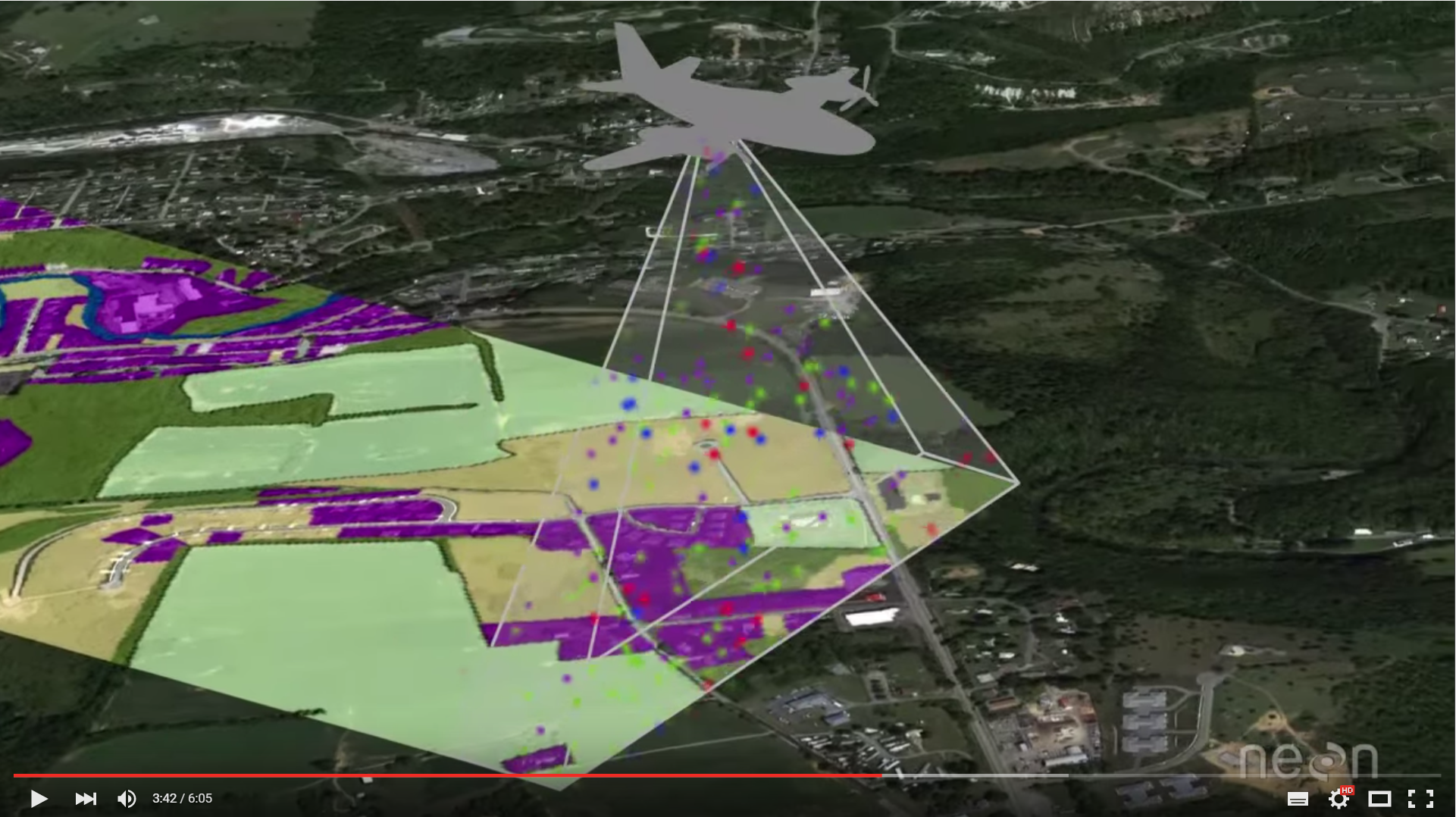
Remote sensing for mapping explained
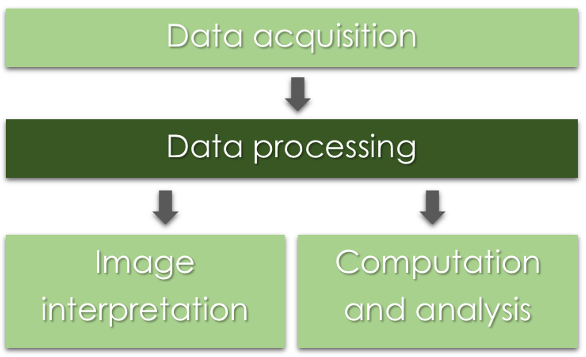
Remote sensing, photogrammerty and GIS
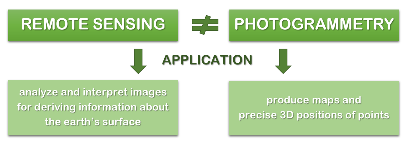
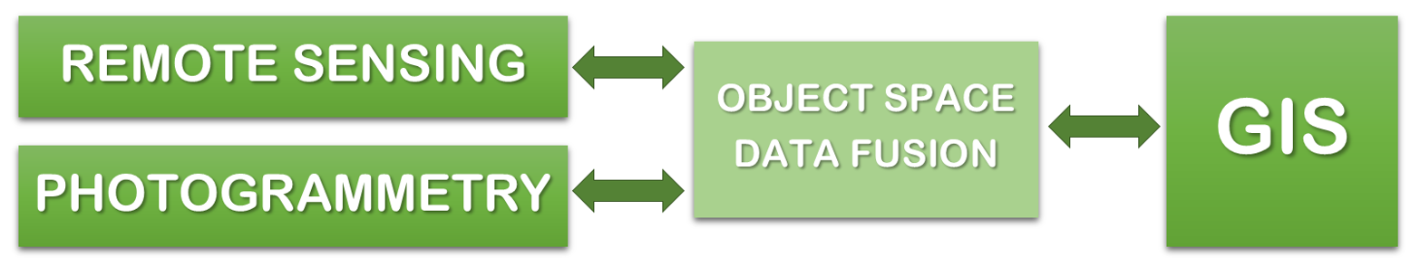
Source of diagrams: Schenk (2005), modified
Photogrammetry
- 3-D coordinate measuring technique that uses PHOTOGRAPHS as the fundamental medium for measurement (the science of taking precise measurements from photographs);
- Can be classified into two types: aerial and terrestrial (close range);
- Aerial Photogrammerty was a crucial development in map making
Vertical and oblique aerial imagery
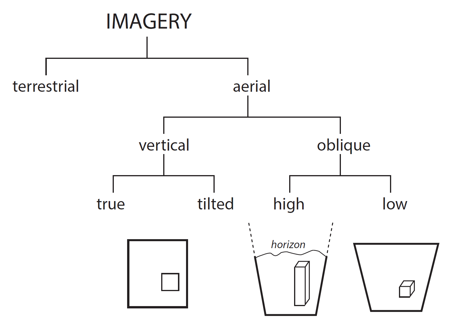
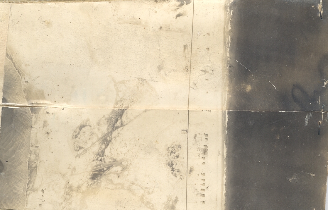
Vertical aerial photography
Jockey's Ridge 1932
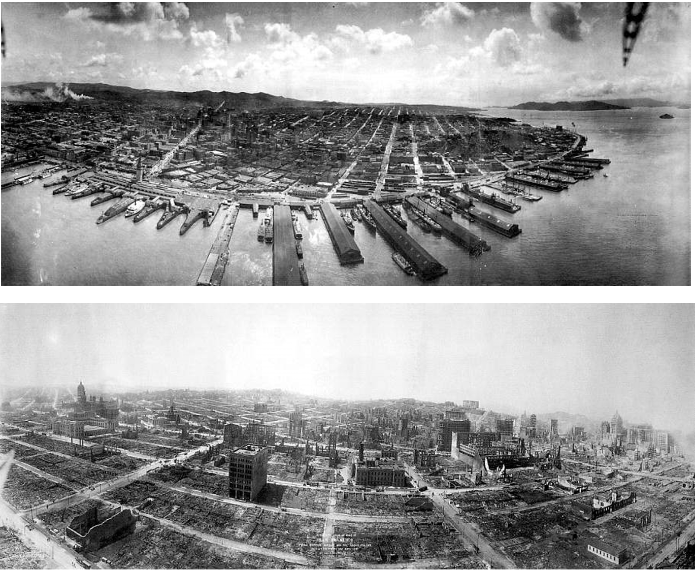
Oblique aerial photography
San Francisco Earthquake, 1906: Note the high distortion
Photogrammetric process
Geometry of aerial photograph
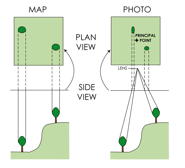
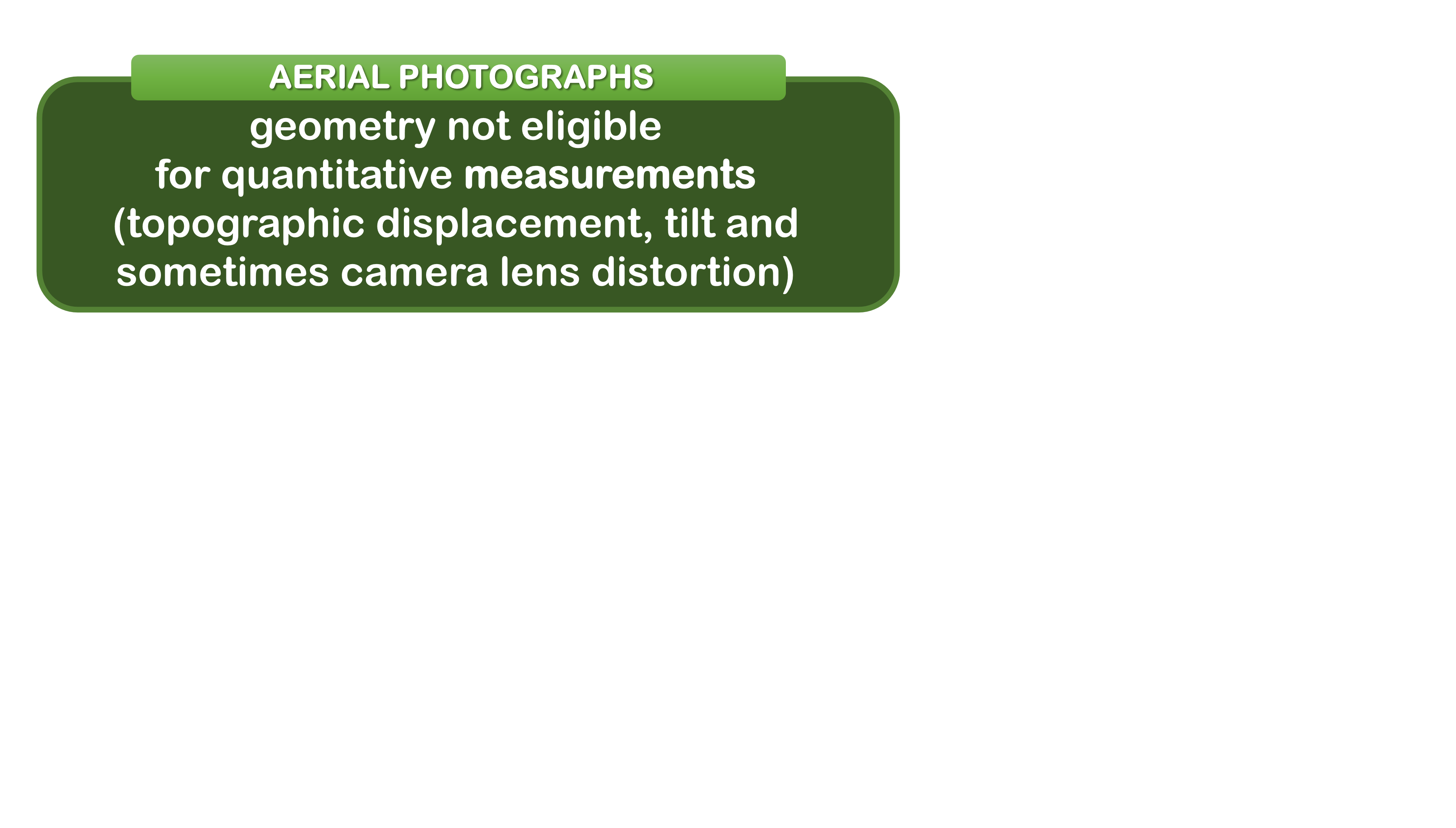
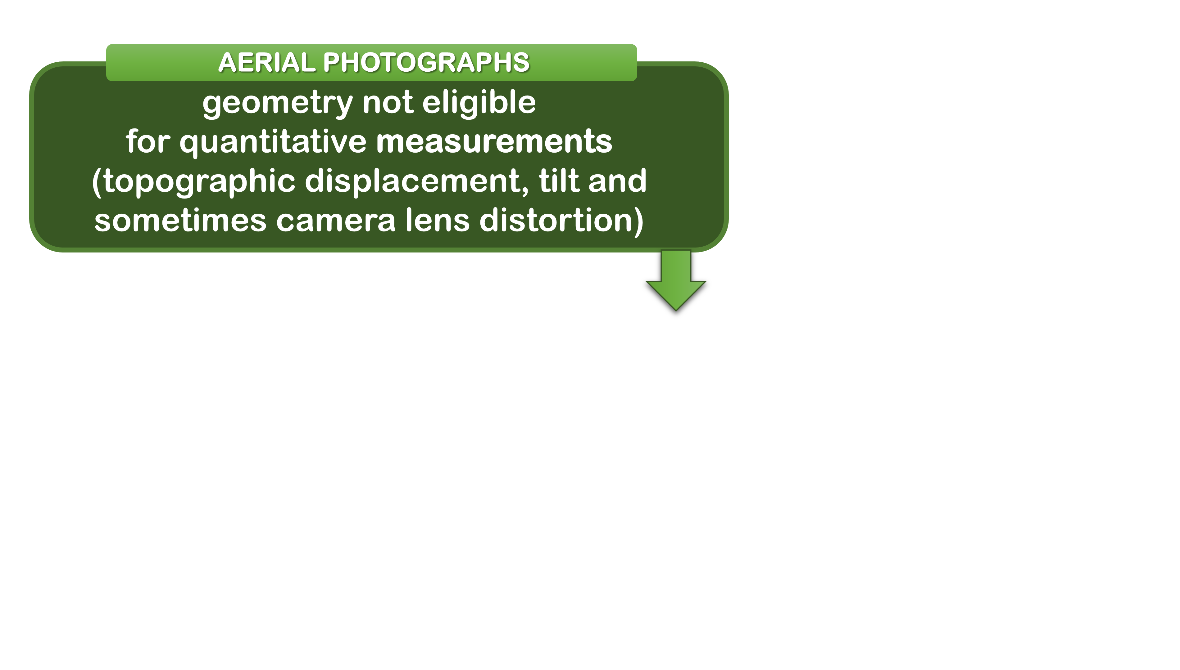
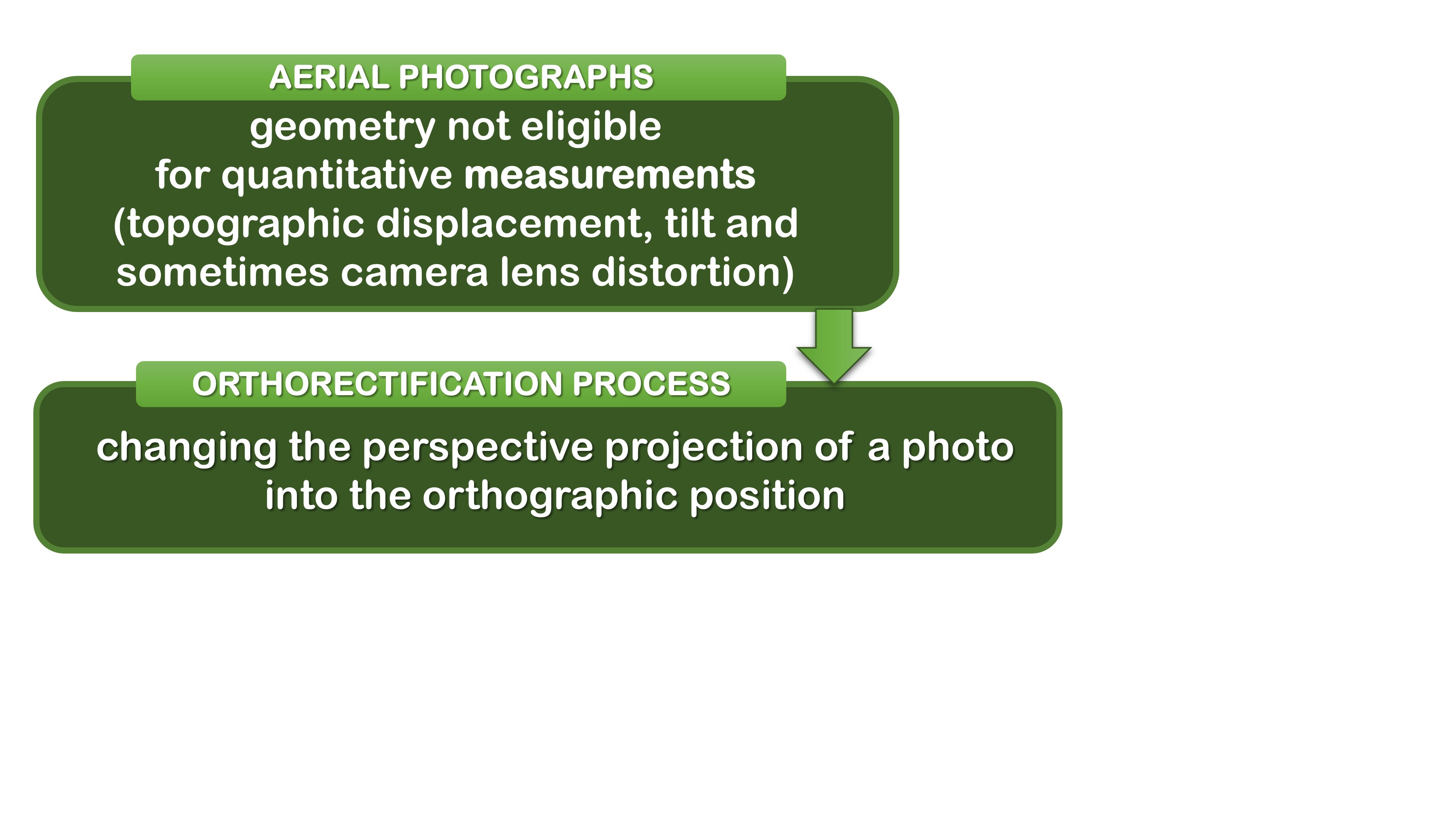
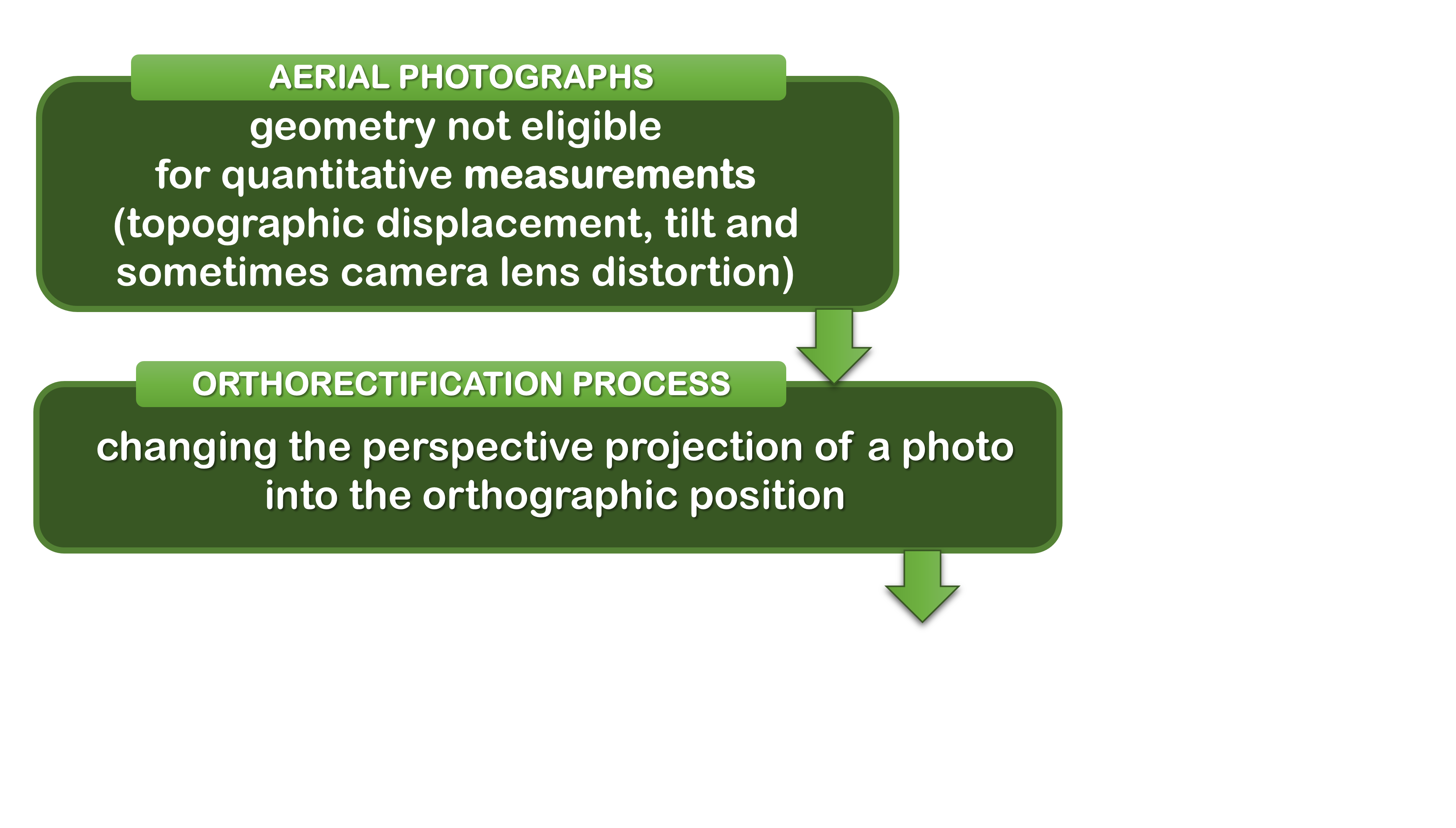
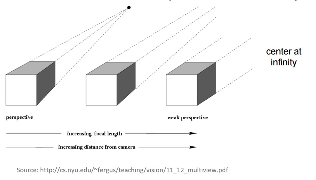
Why do we need to process the images?
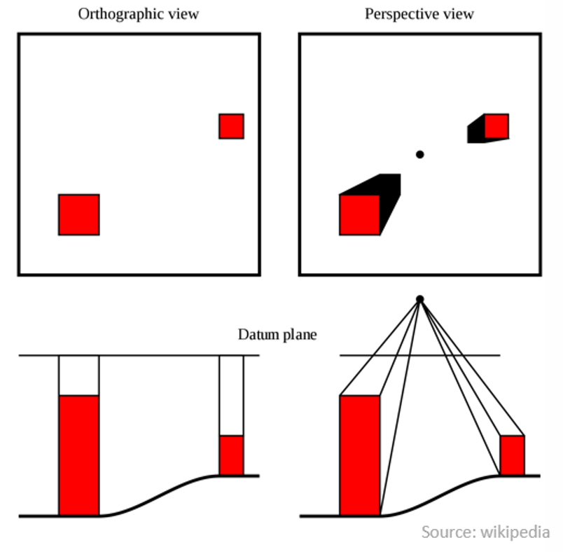
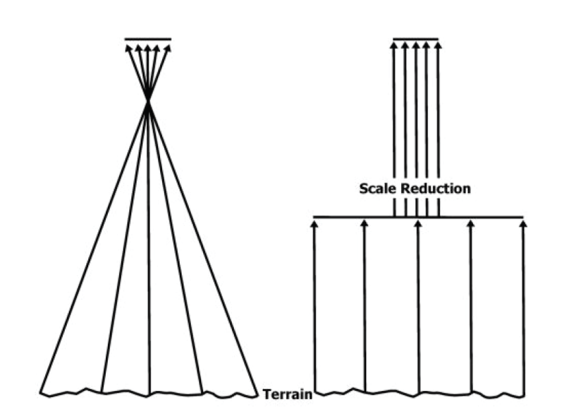
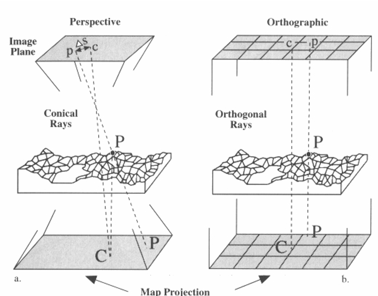
From perspective to orthographic view
Why do we need to process the images?
Perspective and relief distortion
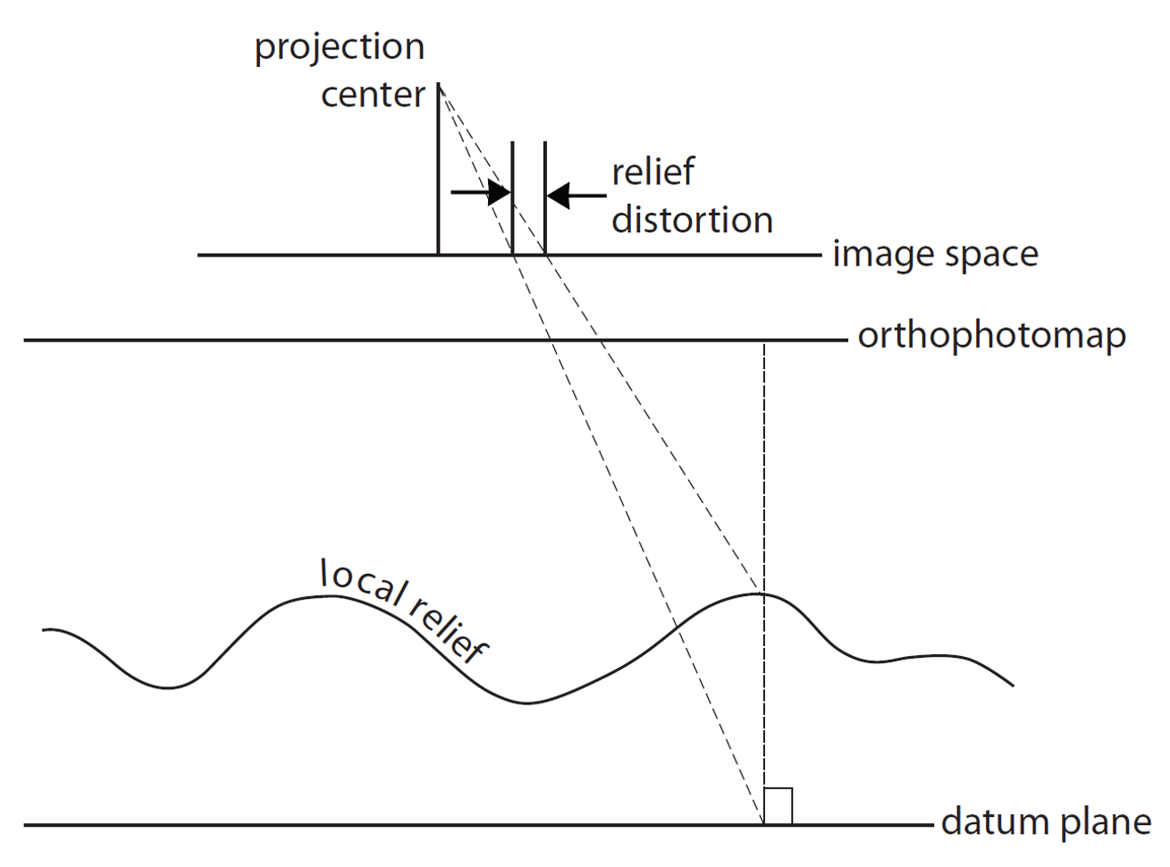
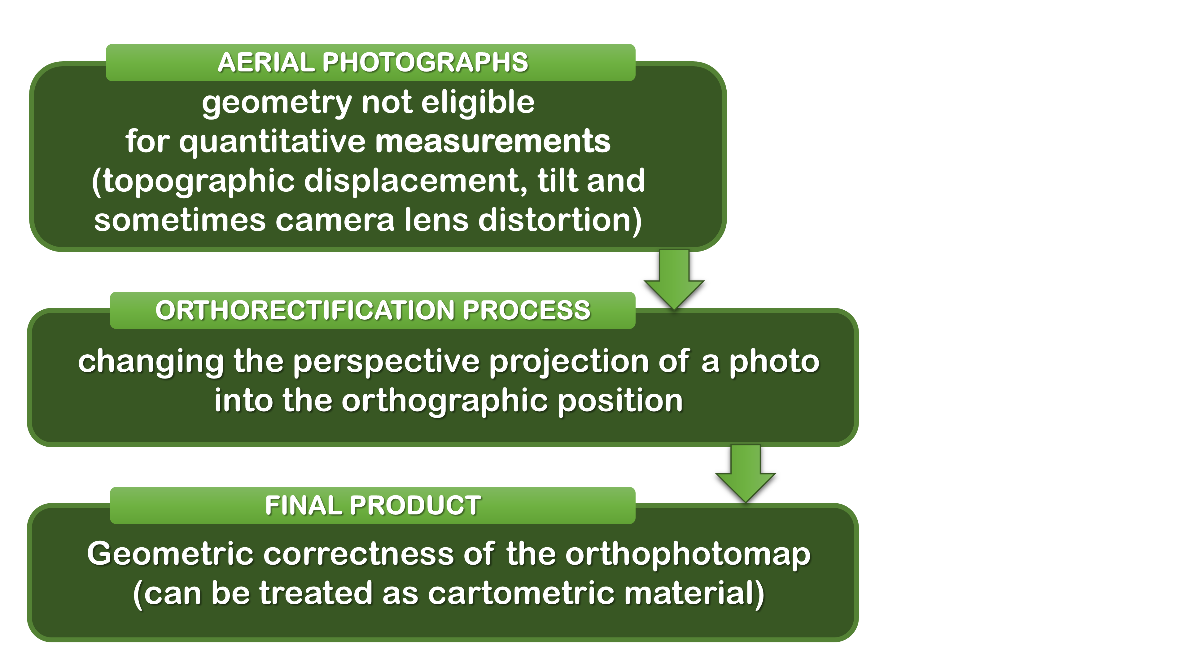
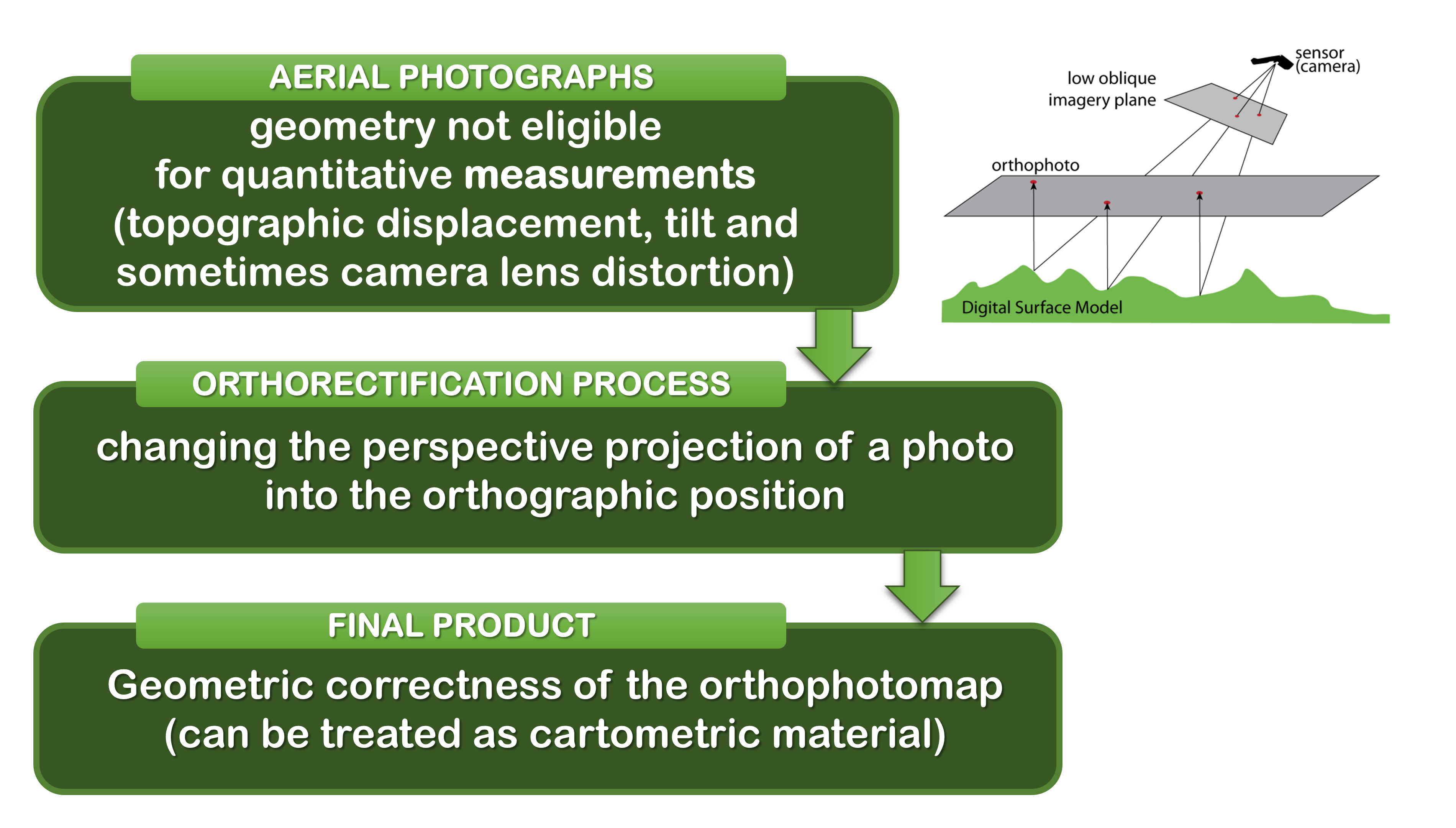
Orthorectification
Process that removes:
- geometric perspective,
- effects of relief displacement,
- optical distortions from the sensor
from a photograph or digital image
The resulting image - an orthophoto or orthoimage.
Orthorectification
Orthorectification
Orthorectification
Orthorectification
Orthorectification
Orthorectification
Orthorectification
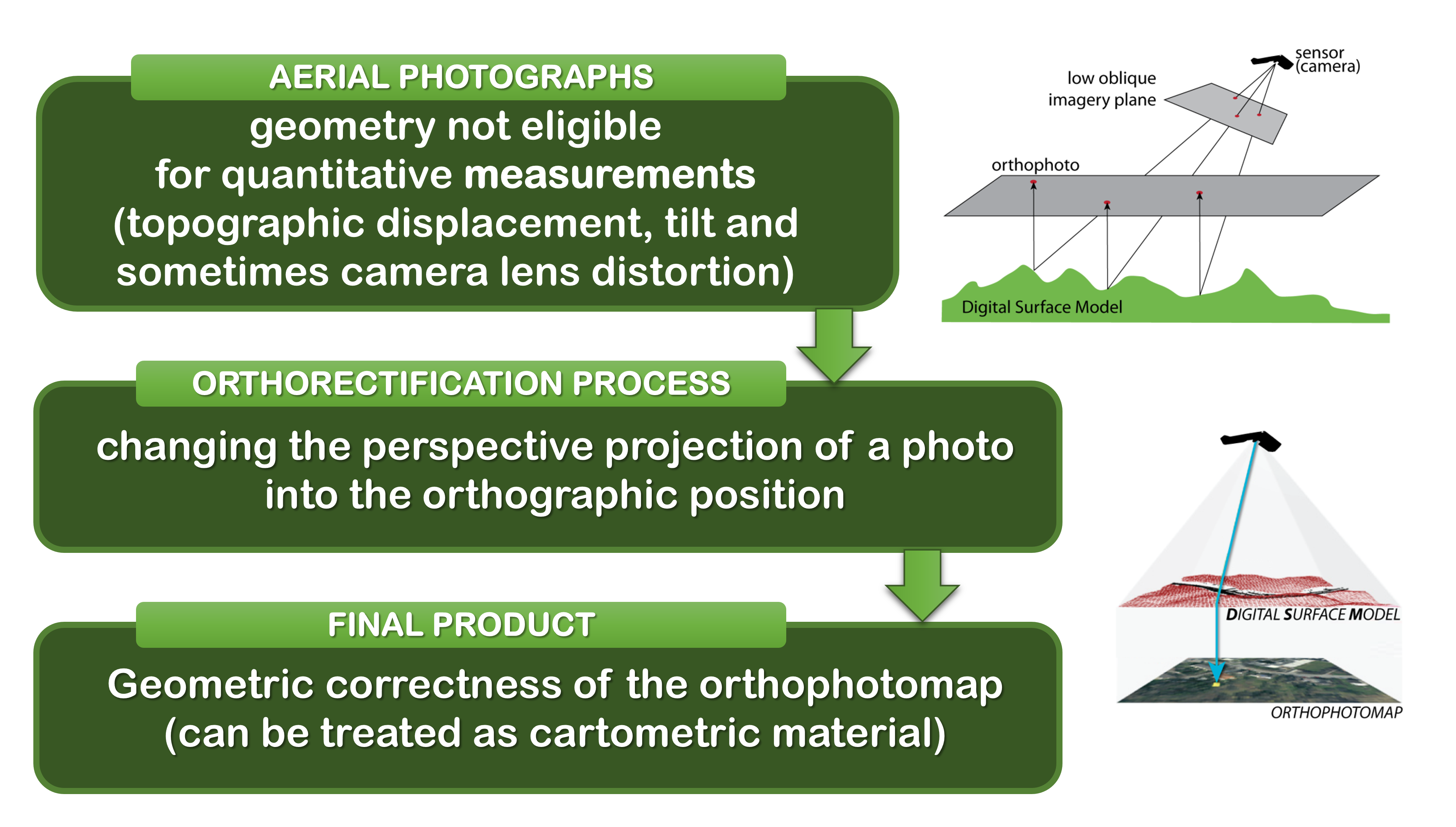
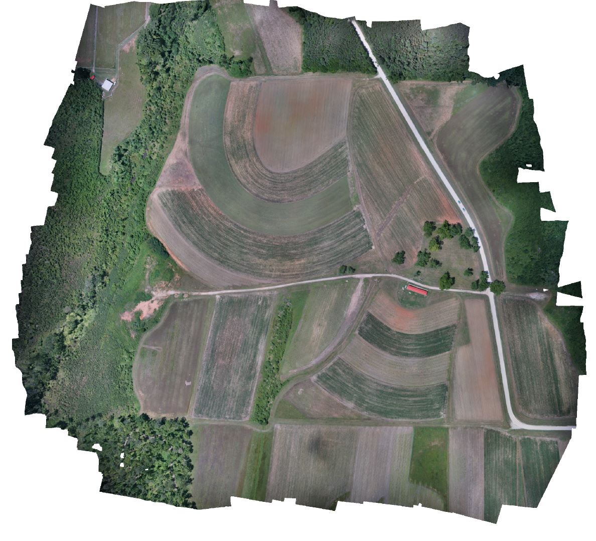
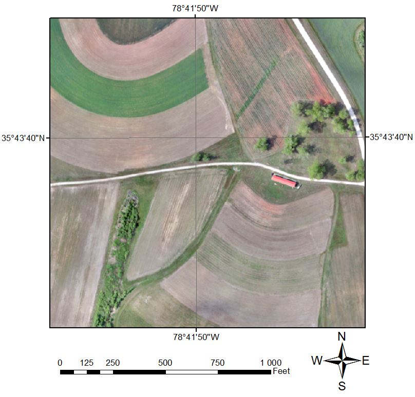
Orthophoto
- Photo that is geometrically corrected and has a uniform scale;
- Can be used to measure true horizontal distances (depending on cartographic projection and spatial extent)
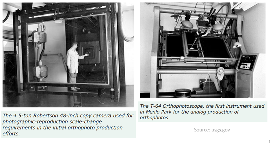
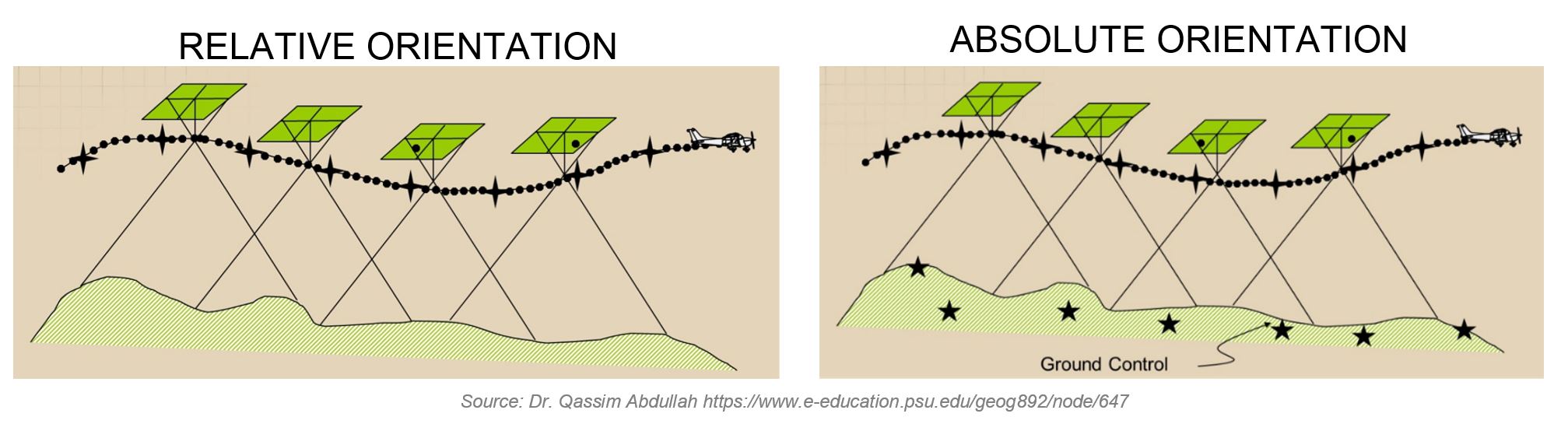
How do we get there?
Old way: analogue
Now: digital

What do we need?
- Digital imagery with sufficient overlap;
- (Digital elevation model to remove the relief distortion)
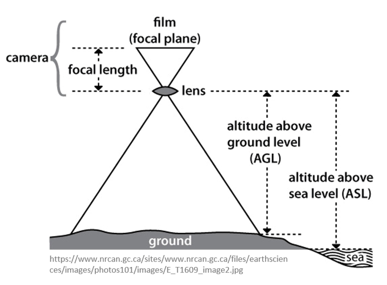
- (Exterior orientation parameters from aerial triangulation or Inertial Measurement Unit (IMU) to remove tilt distortion);
- (Camera calibration report, to transform perspective to ortho projection);
- (Ground Control Points for georeferencing and to reduce distortions);
- Photogrammetric processing software that utilizes collinearity equations.
Parameters 2,3,4 can be estimated from the images - see lecture on Imagery processing
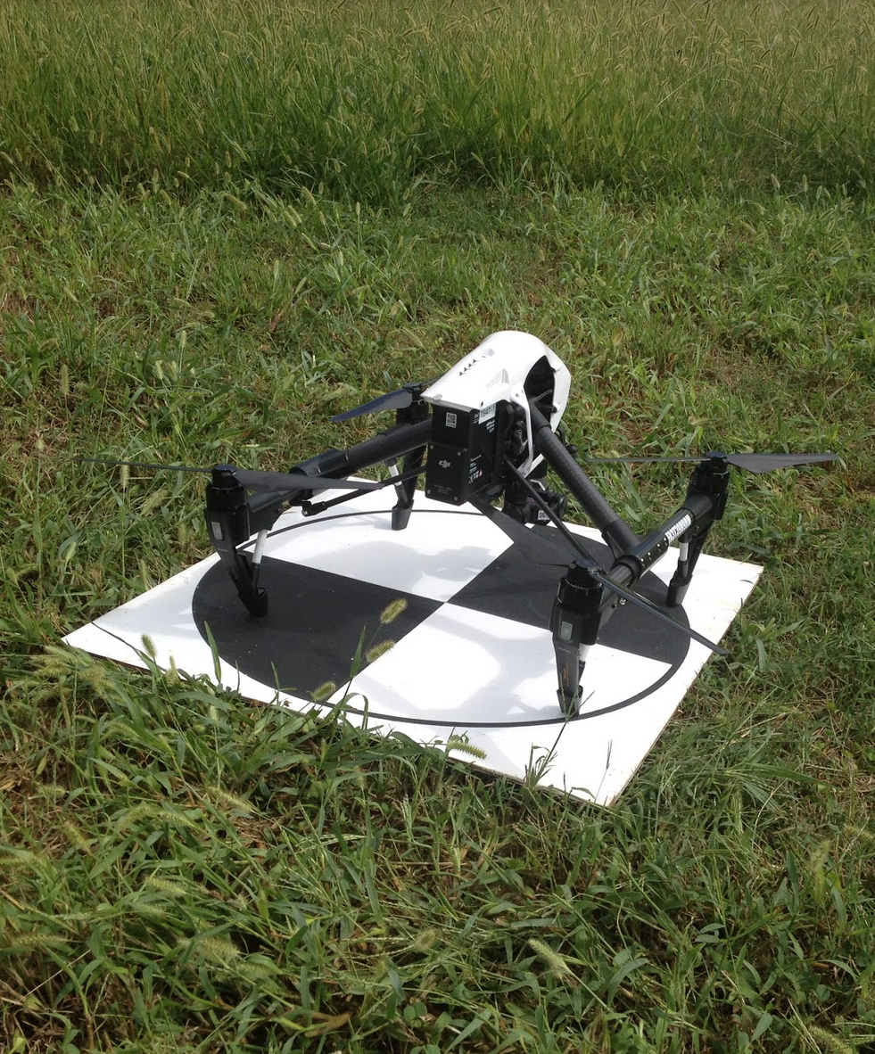
1. Digital imagery
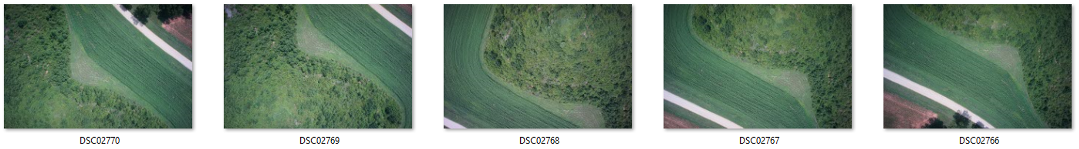
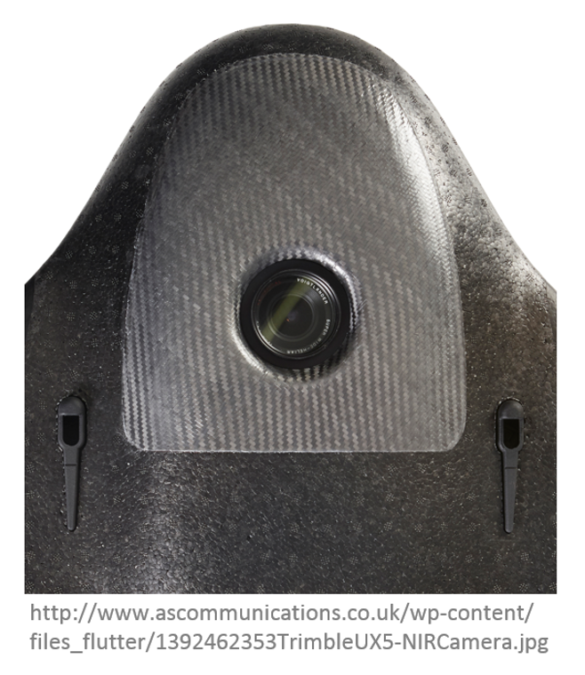
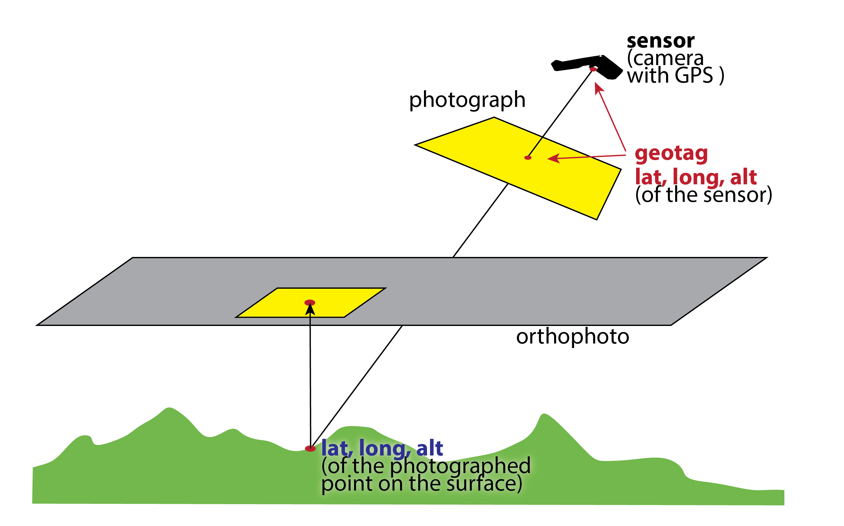
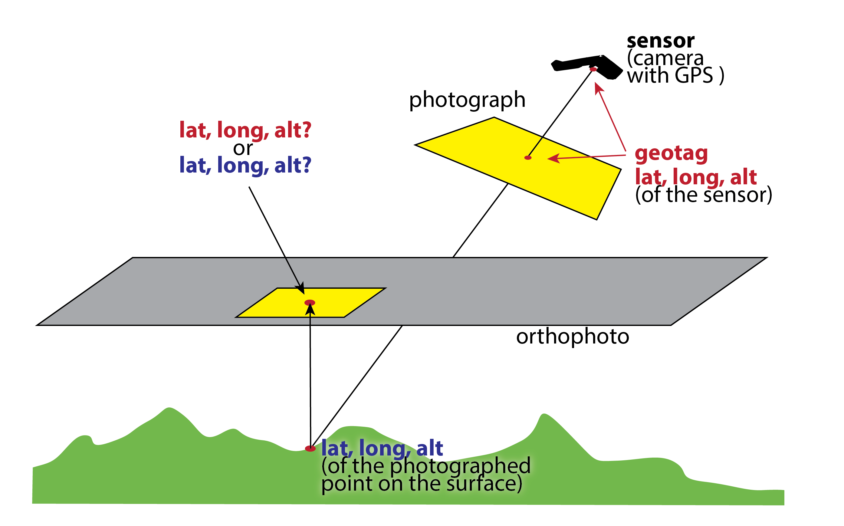
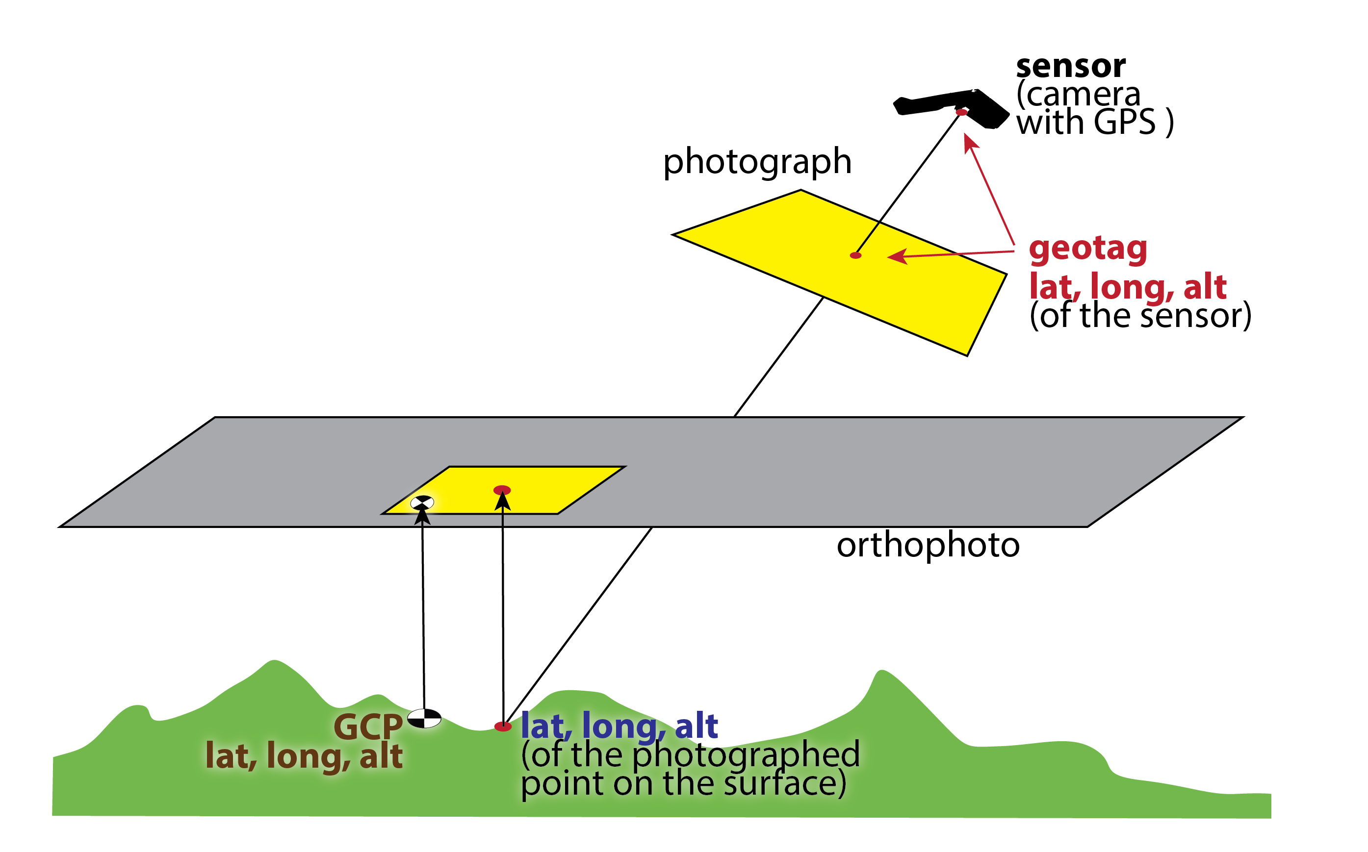
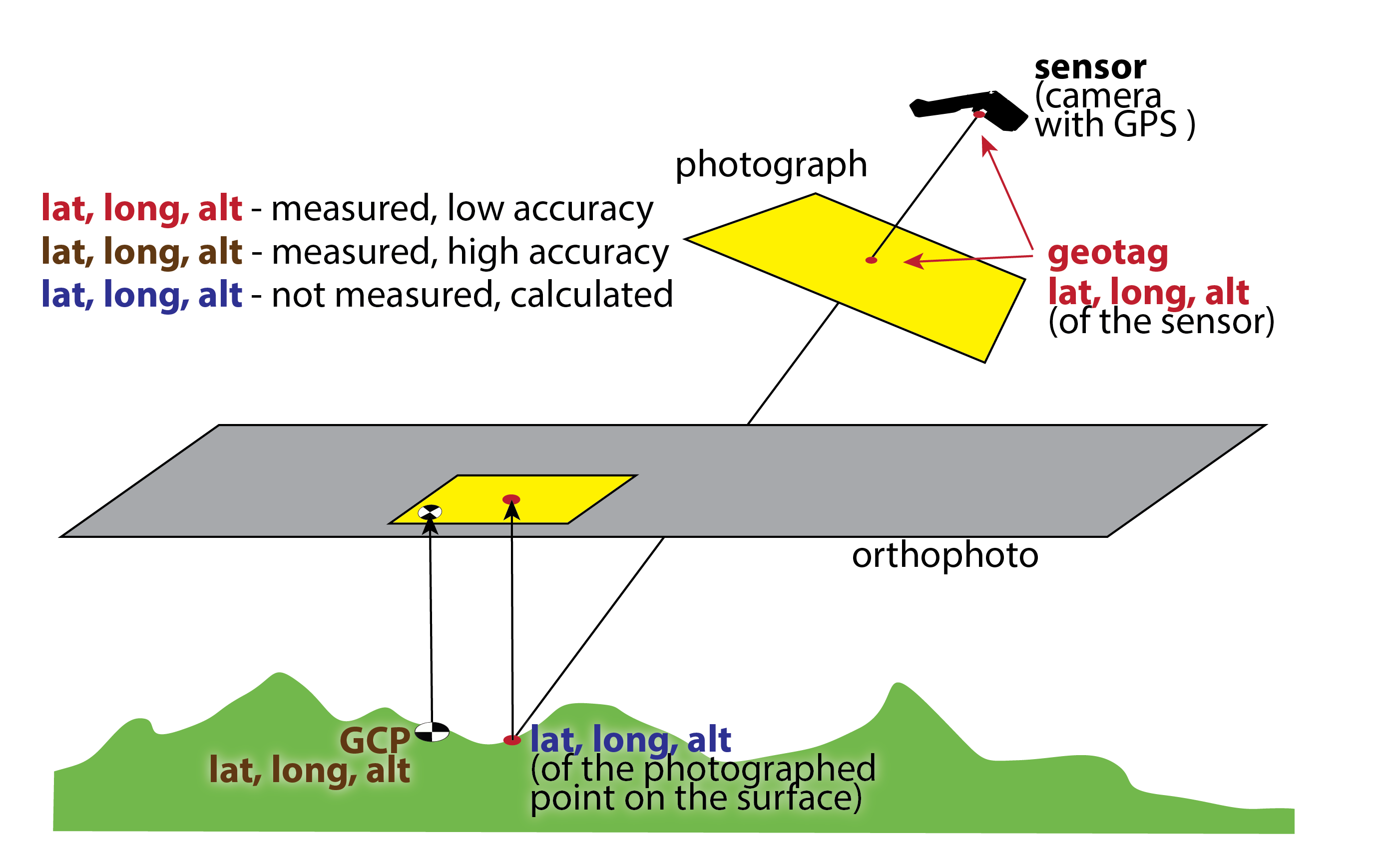
Location of the photo
Geotagging a photograph - associating a photo with a geographical location (latitude, longnitude and usually altitude)
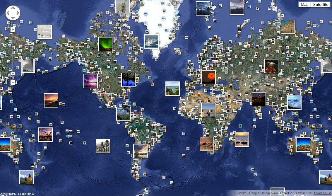
- In theory, every part of a picture can be tied to a geographic location, but in the most typical application, only the position of the sensor is associated with the entire digital image
- GPS in the camera or UAS measures location with very low accuracy
Geotagging
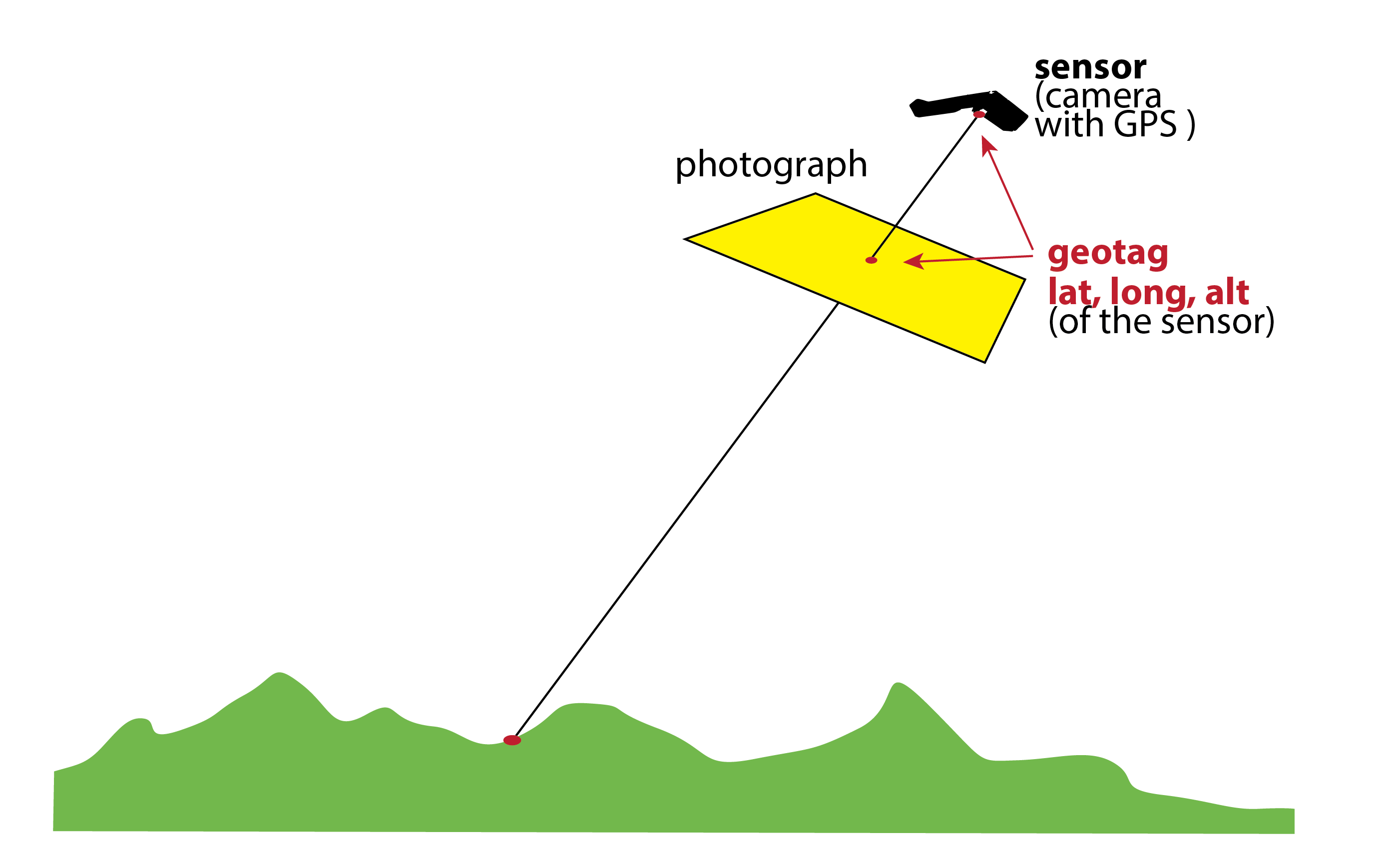
Geotagging
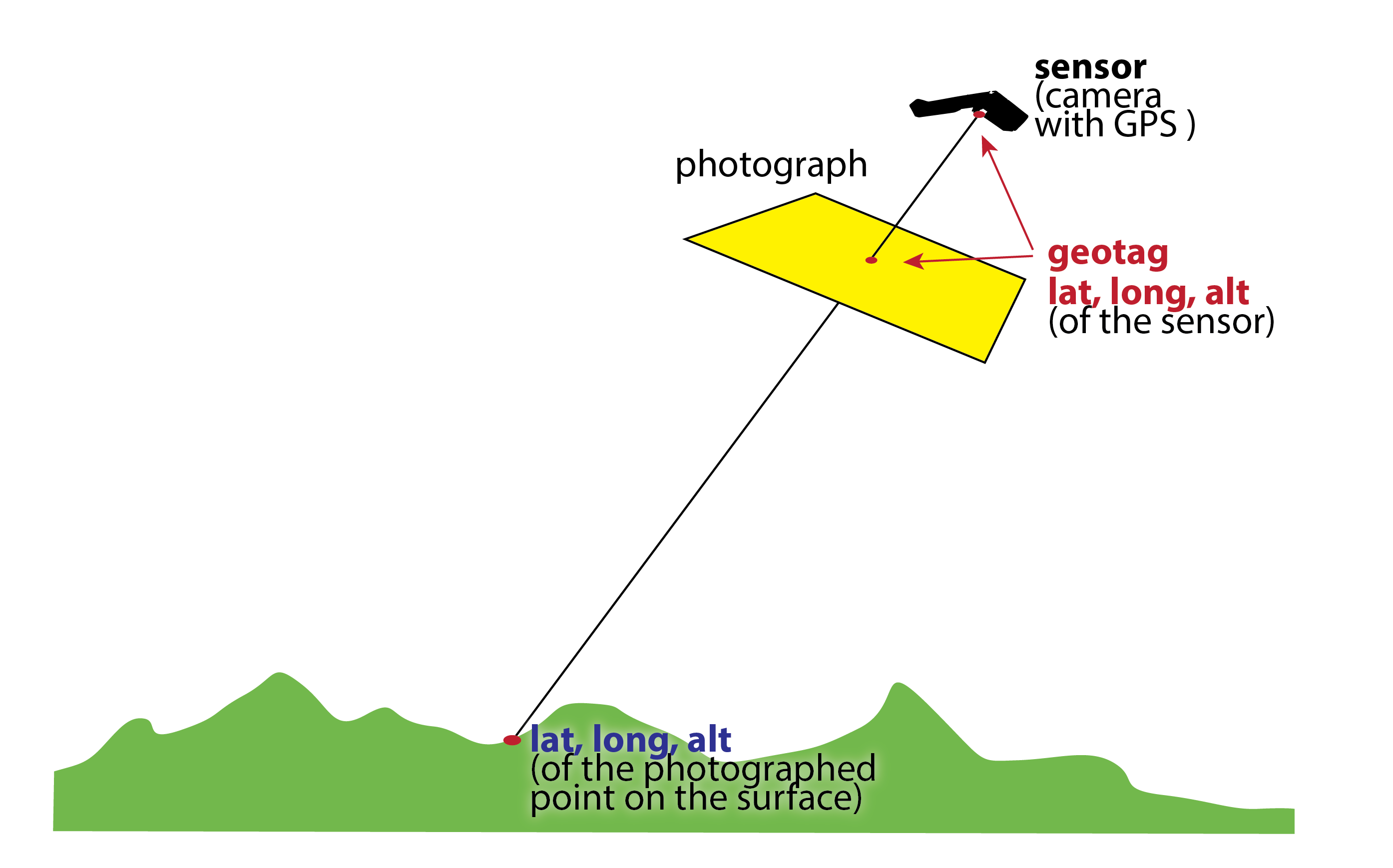
Geotagging
Geotagging
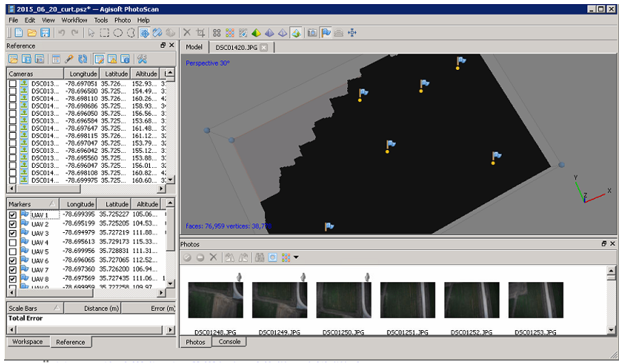
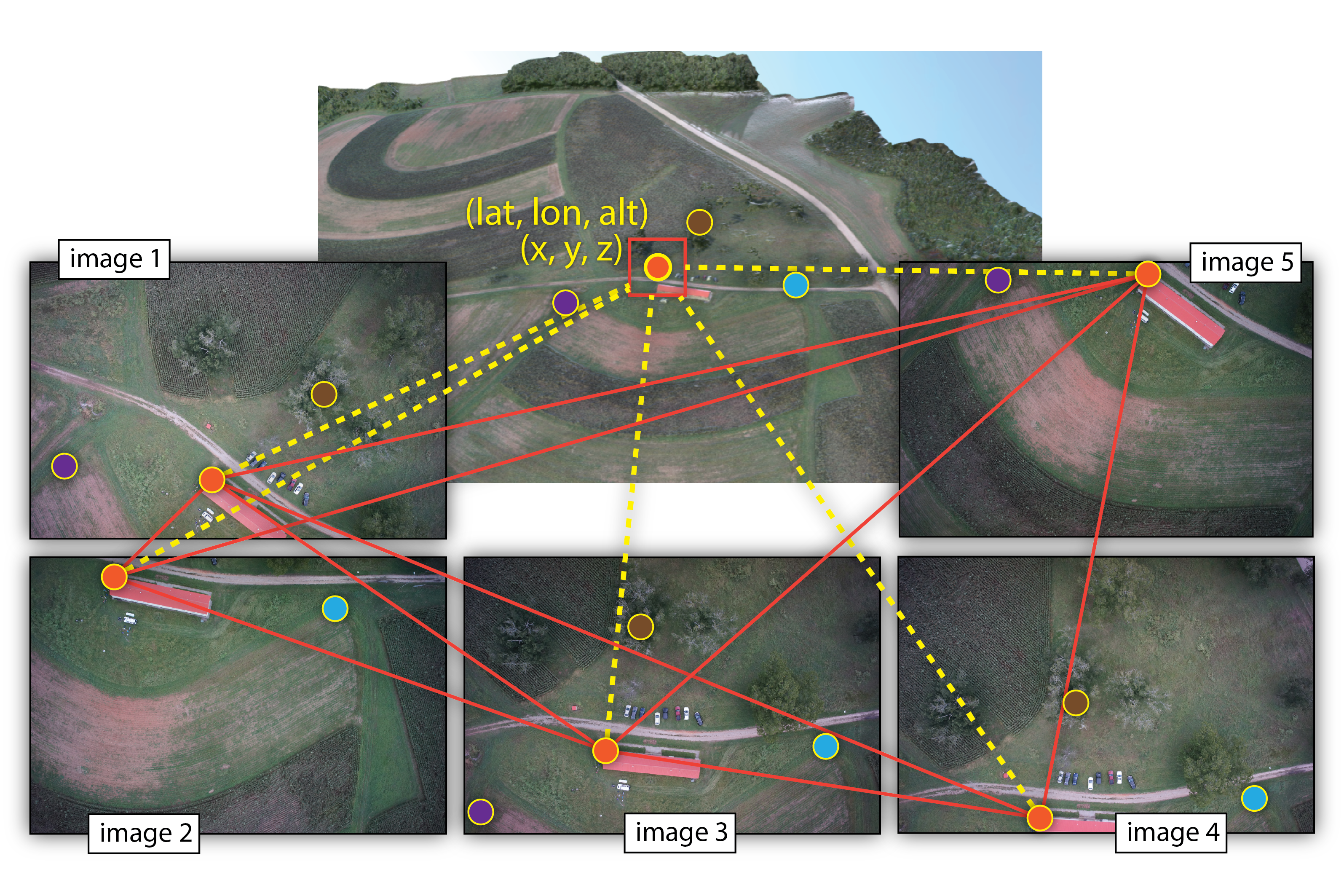
5. Ground Control Points
- GCP - target in the project area with known 3 coordinates (X,Y,Z or lat, long, alt)
- Accurate, well placed and marked GCPs are essential elements for model accuracy and georeferencing
Photo Identifiable:
- any feature on the ground,
- specific (e.g. corners)
- unmovable,
- not covered by vegetation
- it can be surveyed later on.
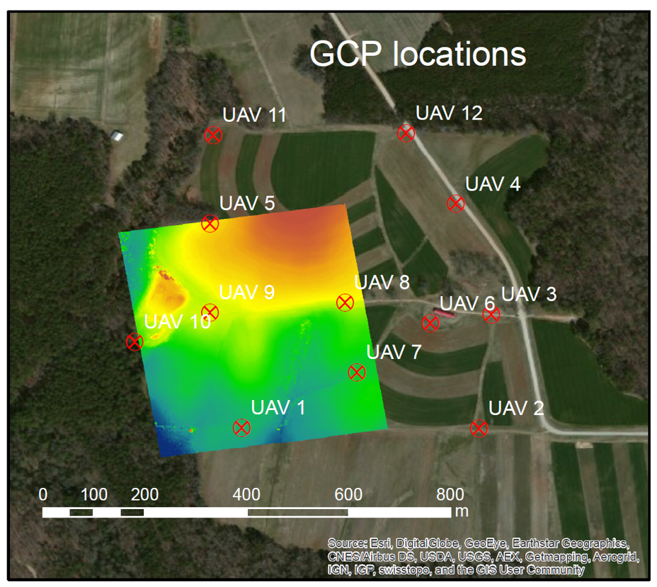
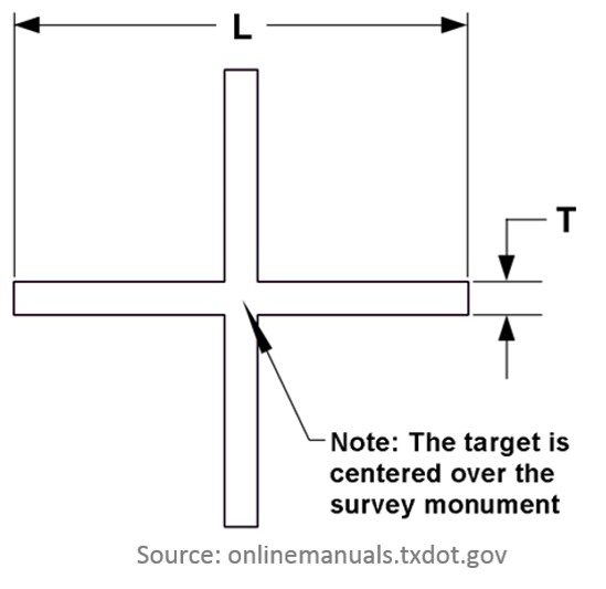
Ground Control Points
Pre-marked (Panels): marking or painting figures or symbols on the ground before the UAS flies
Why Ground Control Points?
- necessary for georeferencing if photos are not geotagged
- improve precision of the model
- important for quality control
Why Ground Control Points?
Why Ground Control Points?
Why Ground Control Points?
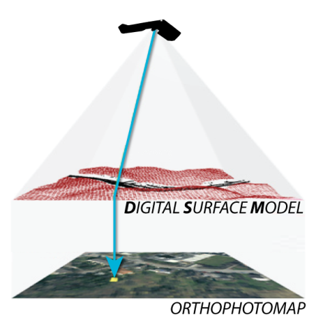
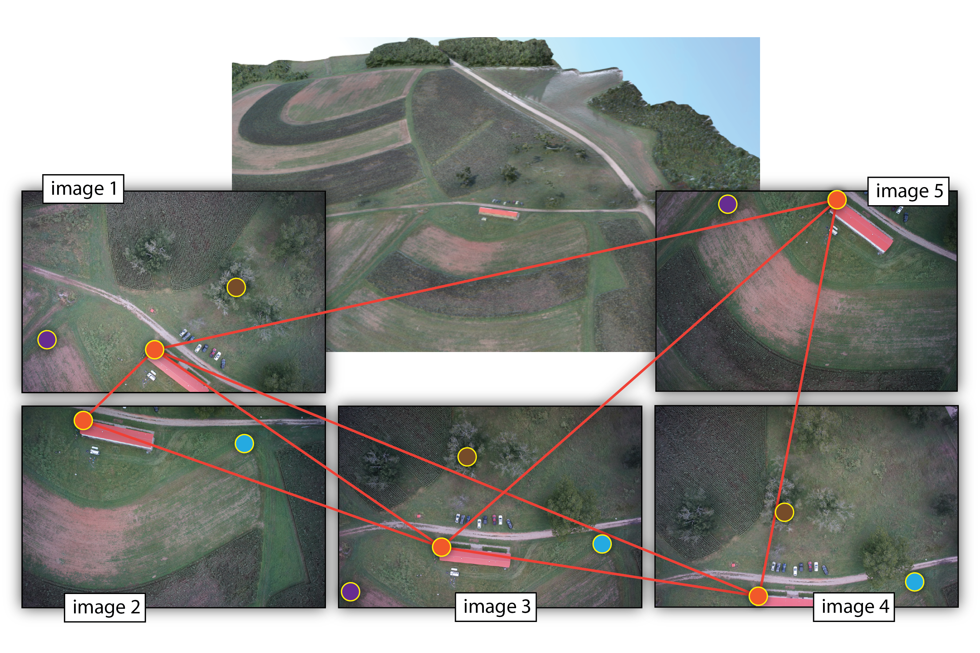
From 2D images to a 3D model
- orthophoto is a 2D image
- elevation data are derived as part of orthorectification process
- exact camera parameters and manually identified GCPs on the images were needed to derive a DEM
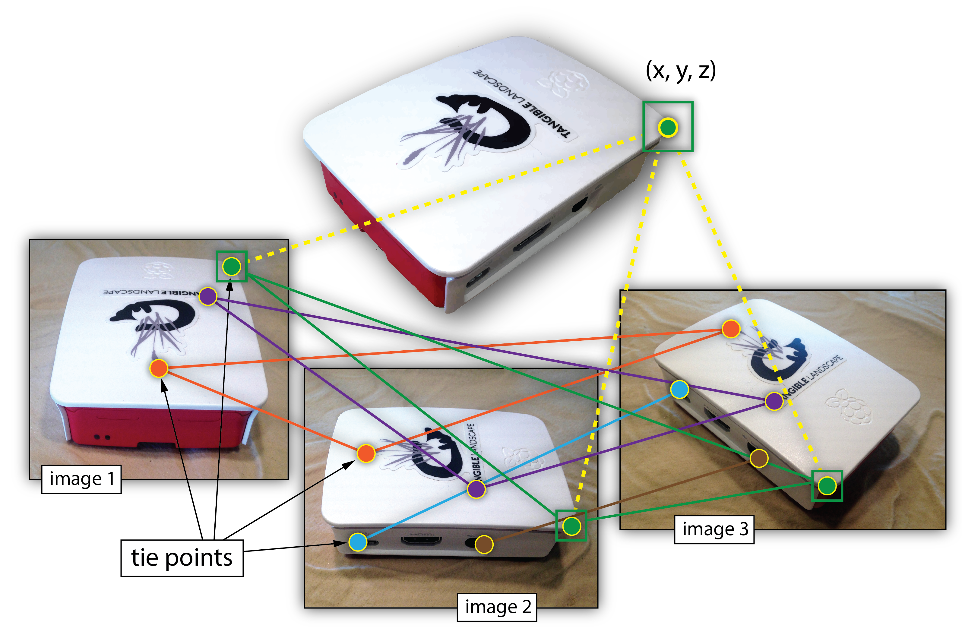
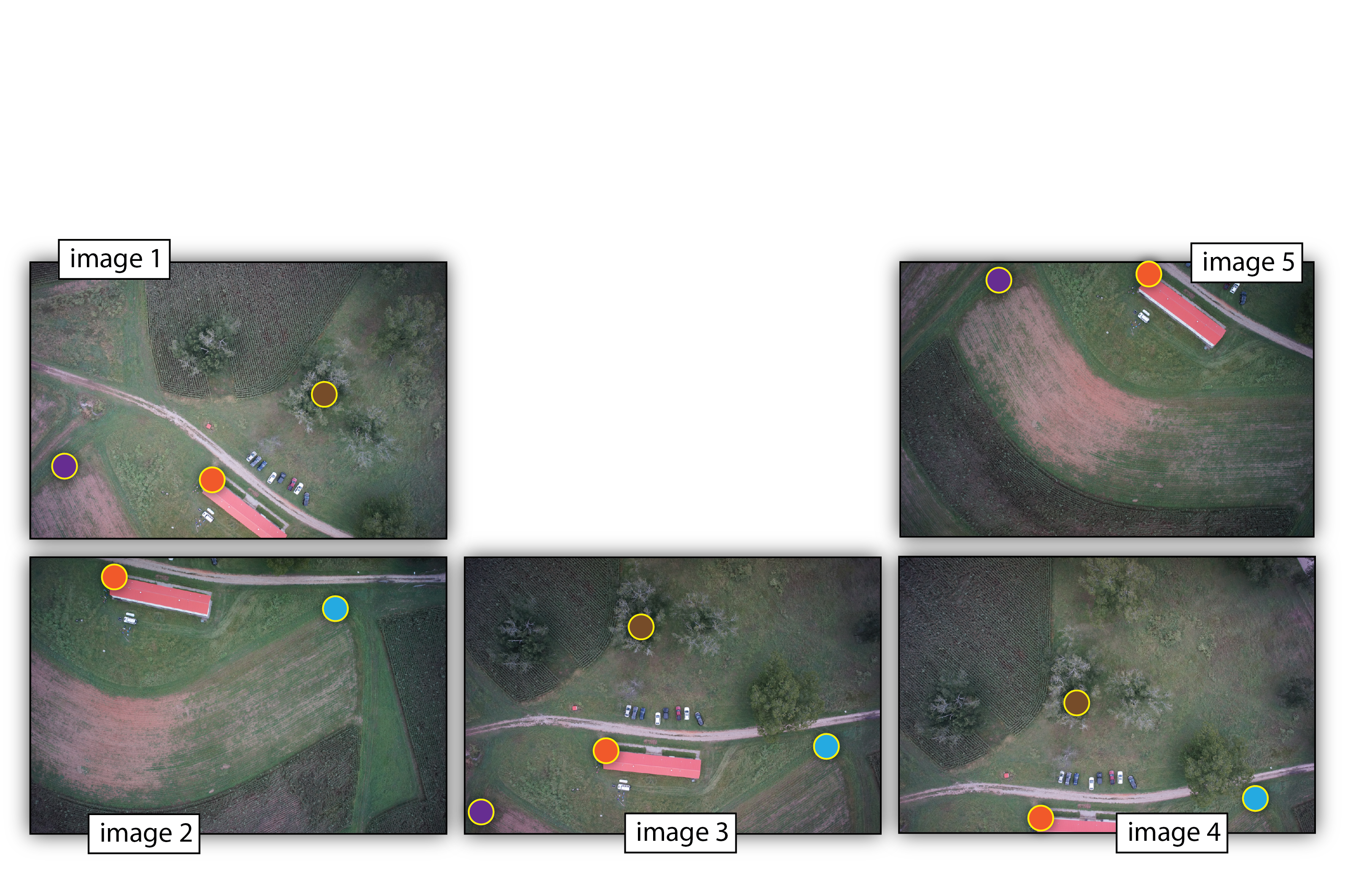
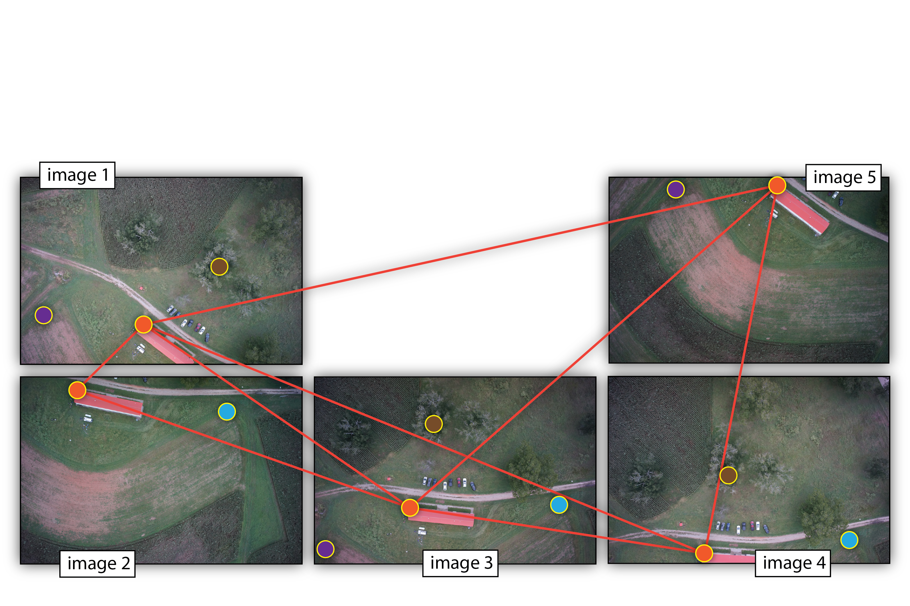
- Structure from Motion: automated point matching, camera parameter estimation and 3D model generation
Multiple-view geometry
- Scene geometry (structure):
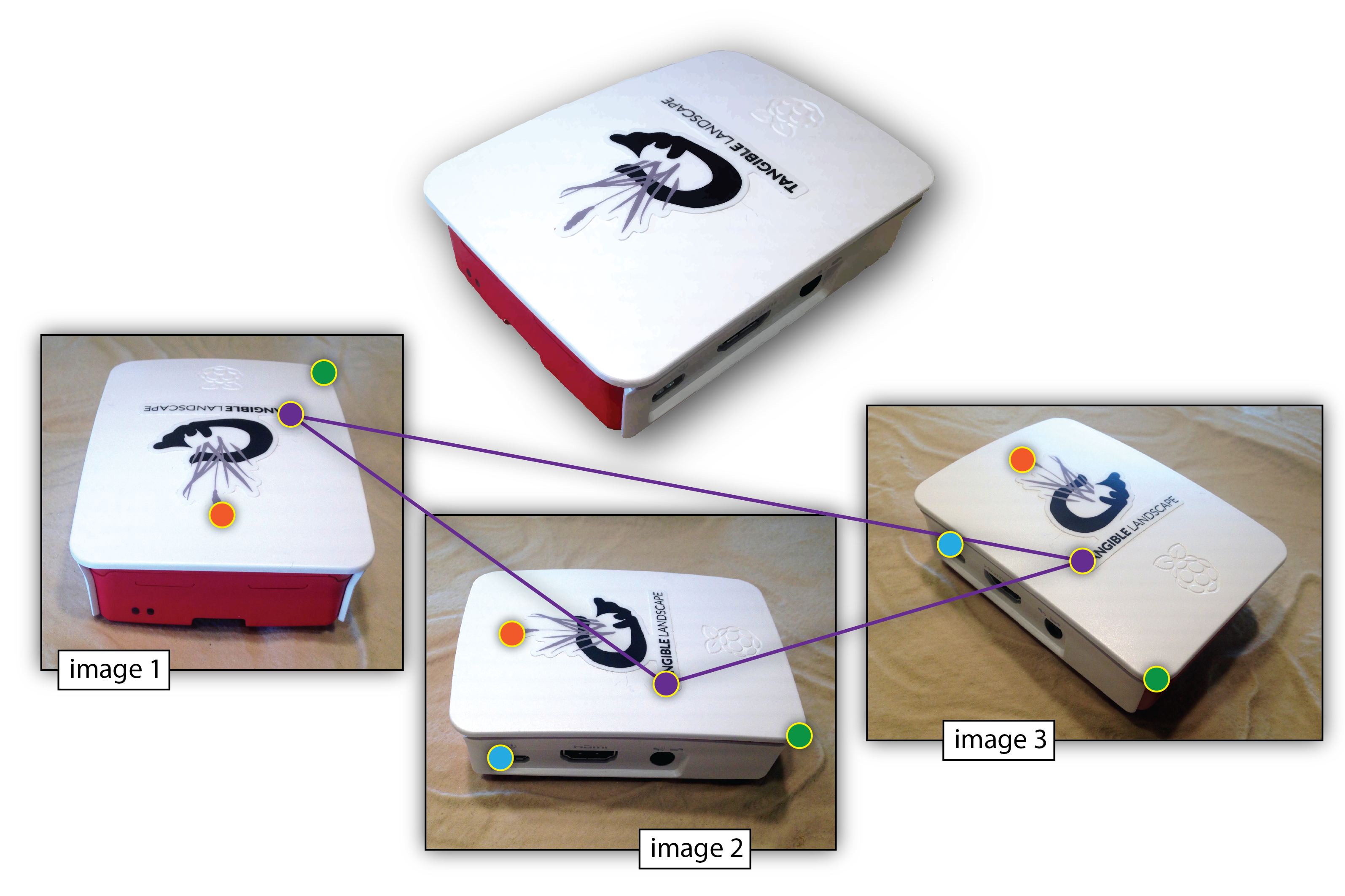
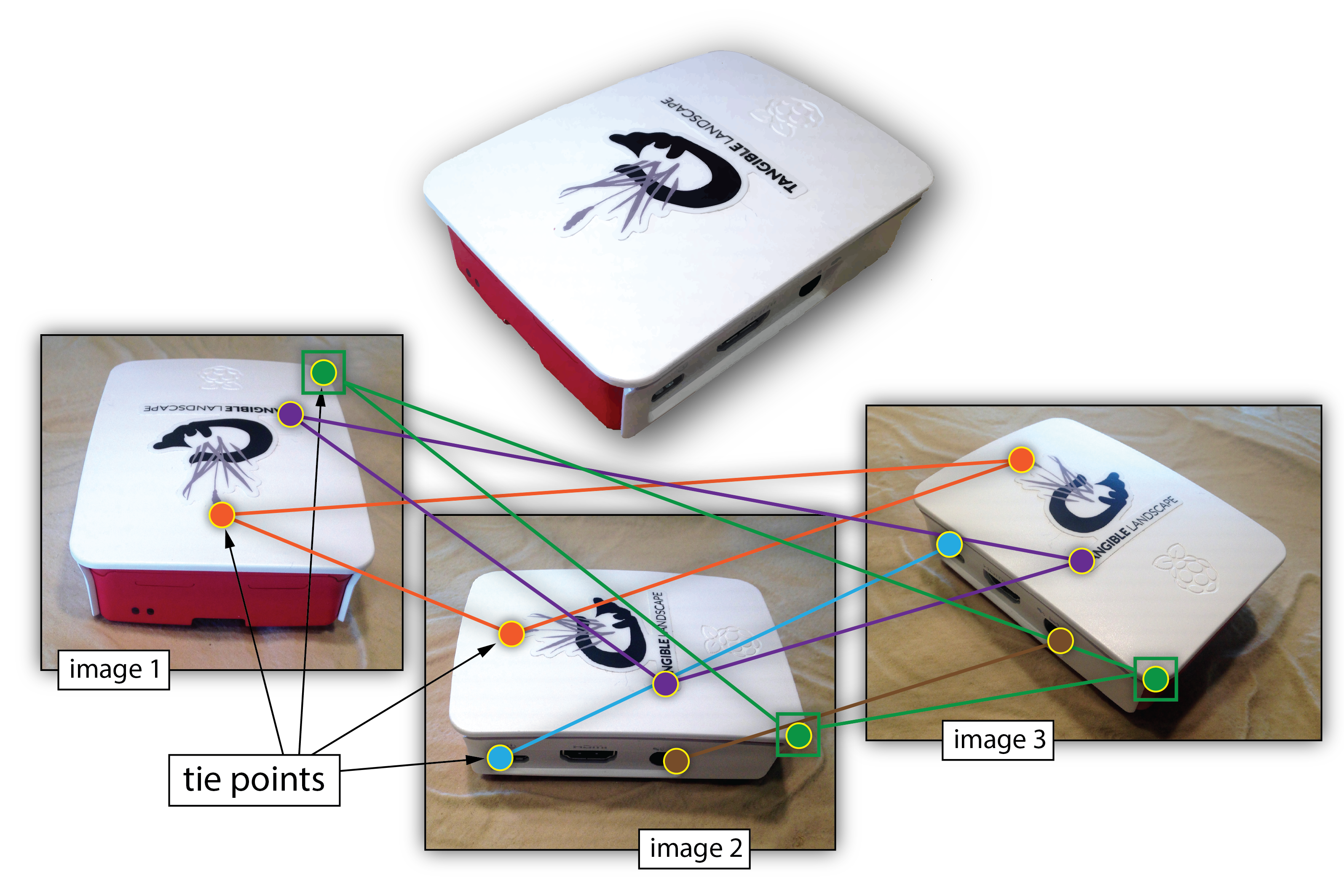
Given 2D point matches in two or more images, where are the corresponding points in 3D? - Correspondence (stereo matching): Given a point in just one image, how does it constrain the position of the corresponding point in another image?
- Camera geometry (motion): Given a set of corresponding points in two or more images, what are the camera matrices for these views?
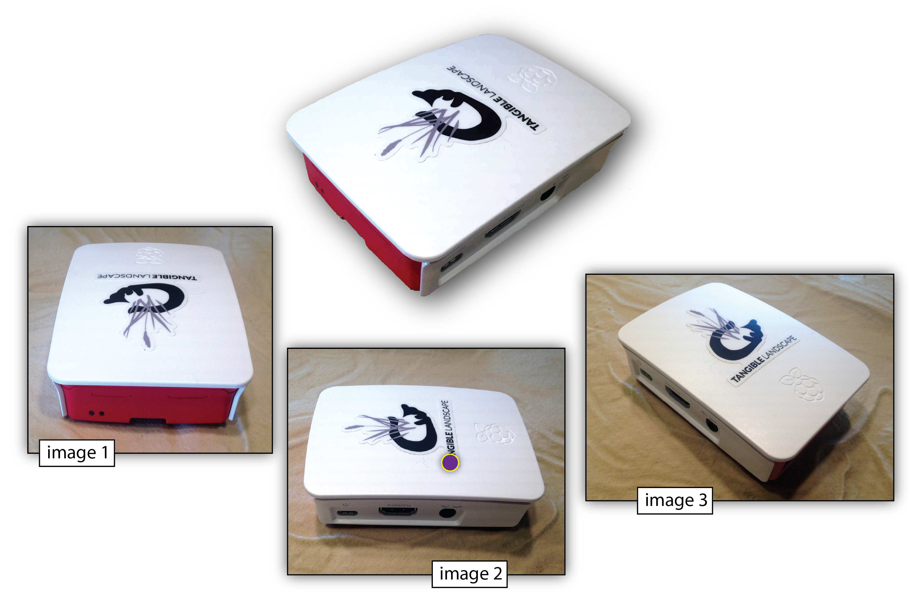
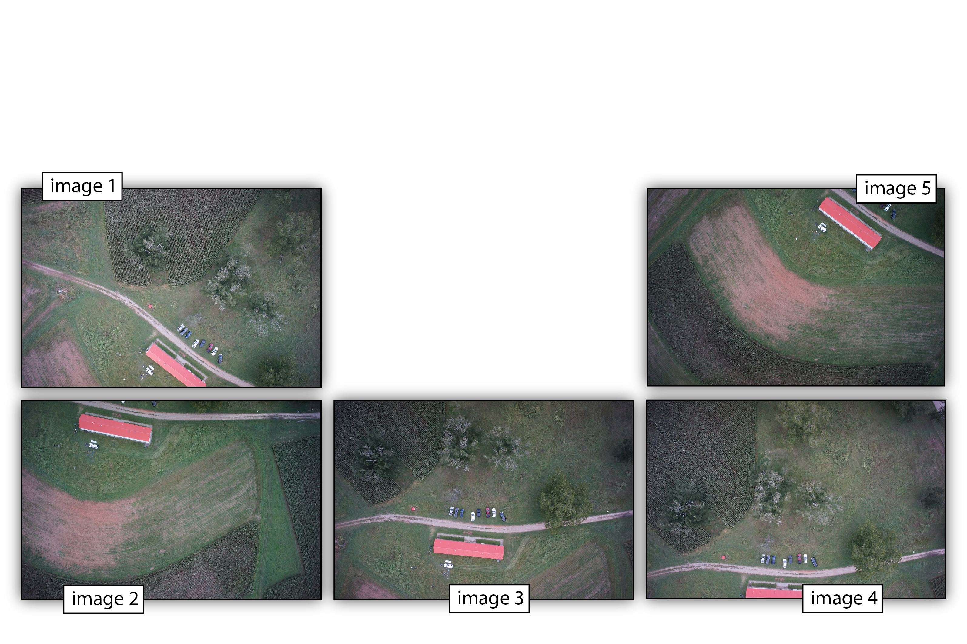
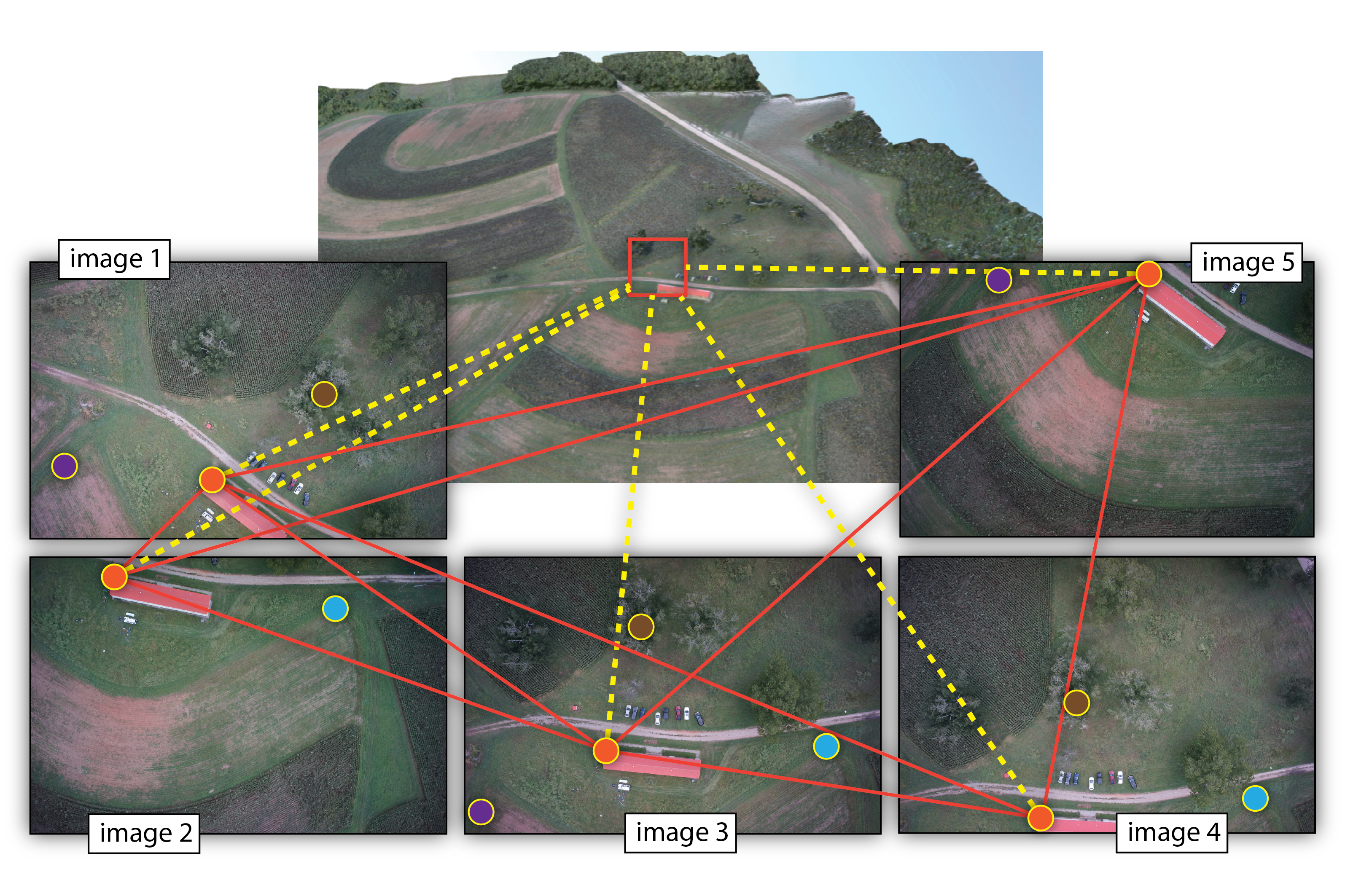
Structure from Motion (SfM)
- range imaging technique,
- process of estimating 3D structures from overlapping 2D image sequences,
- may be coupled with local motion signals
Structure from Motion (SfM)

Structure from Motion (SfM)
Structure from Motion (SfM)

Structure from Motion (SfM)

Structure from Motion (SfM)
Structure from Motion (SfM)

Structure from Motion (SfM)
Structure from Motion (SfM)

Structure from Motion (SfM)
Structure from Motion (SfM)
Structure from Motion (SfM)
Structure from Motion (SfM)
Structure from Motion (SfM)
Structure from Motion (SfM)
Structure from Motion (SfM)
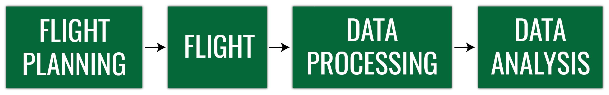
UAS Photogrammetric process
Throughout the whole process, it is important to remember
- What is the aim or the project? and
- What will be the data used for?
What we have learned
- What is remote sensing and photogrammetry
- Properties of aerial image
- Why do we need orthrectification to measure from aerial images
- What process allows us to extract 3D data from series of overlapping 2D images
