Analysis of the processing outputs
UAS Operations and Analytics Workshop
Visualization of the outputs
- all georeferenced poutputs - orthophoto, DSM and pointcloud can be displayed and analyzed in the GIS software
- 3D model can be loaded onto 3D modeling software
- There are online tools enabling rapid visualization of 3D content
Point cloud - plas.io
plasi.io an in- browser point cloude rendering tool

3D model - Sketchfab
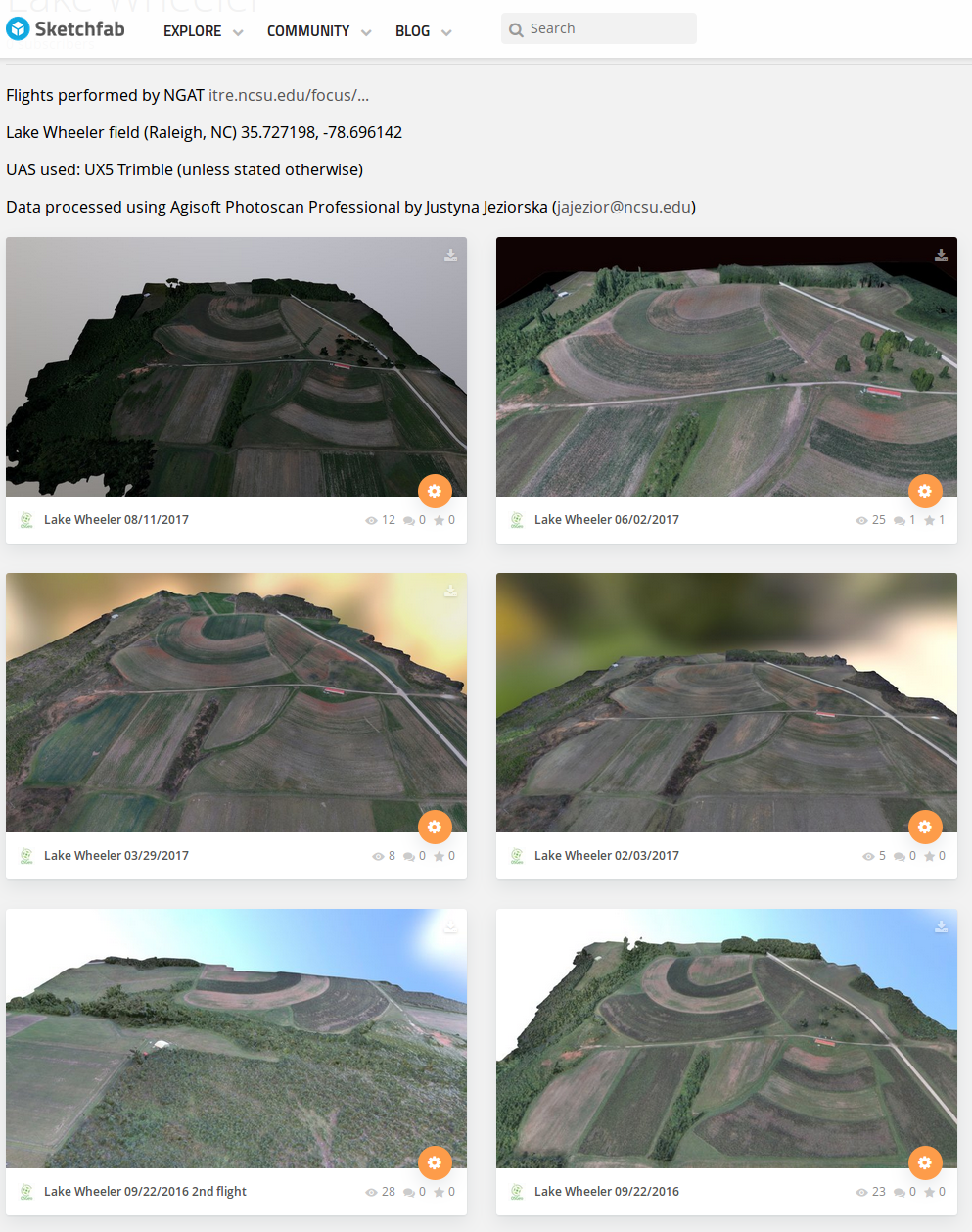
Sketchfab is a platform to publish, share and discover 3D, VR and AR content
OSgeoForALl models on sketchfab
- Free account has limitations
- Pro account available for .edu domains
Analyzing the processing report

Includes:
- Orthophoto and digital elevation model sketch;
- Camera parameters and survey scheme
- Tie points data export (matching points and panoramas)
- Image overlap statistics
- Camera positioning error estimates
- Ground control point error estimates
- Processing parameters
Orthophoto

Survey data

Ground Control Points

Ground Control Points
Camera calibration report

Camera calibration report

Camera calibration report

Camera calibration report

Camera calibration report

Camera calibration report

Camera calibration report

Analyzing the processing report

- While carrying out photo alignment PhotoScan estimates both internal and external camera orientation parameters, including nonlinear radial distortions.
Tools > Camera calibration
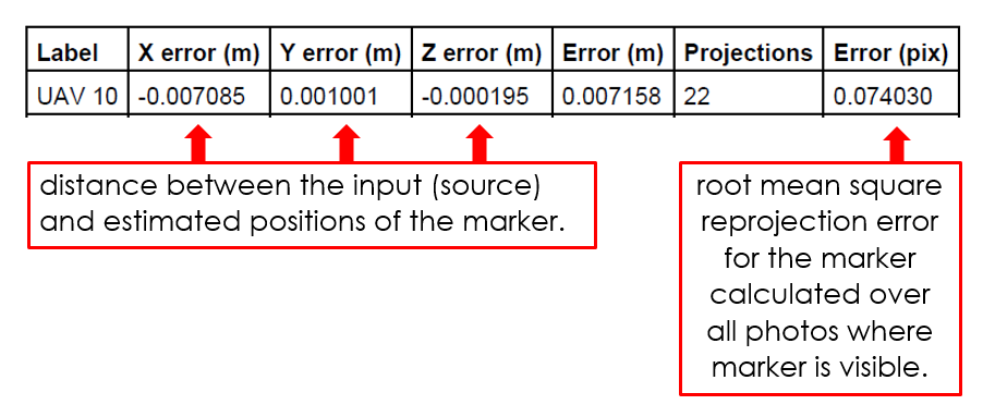
Image residuals

Image residuals

Image residuals

Image residuals

Image residuals
This reprojection error is equivalent to the root mean square (RMS) image residuals used in photogrammetric literature
More on image residuals in this article

Flight path

Flight path in 3D

Digital Surface Model

DSMs comparison by software

GCPs

'Bowl effect'
effect can be introduced during photo alignment, in case camera calibration estimates are inaccurate

'Bowl effect'
effect can be introduced during photo alignment, in case camera calibration estimates are inaccurate


'Bowl effect'- solutions to the problem
- If camera calibration is known in advance- it can be loaded in PhotoScan and fixed during photo alignment.
- Optimization procedure - recommended approach
- based on camera or GCP coordinates
- performed after photo alignment
- is recommended to perform optimization based on ground control data in any case, even if precalibrated cameras are used
Optimization

What is an optimization?
- PhotoScan performs full photogrammetric adjustment taking into account additional constraints introduced by ground control data
- Extrinsic and intrinsic parameters for all cameras are optimized at this step, in contrast to the simple 7-parameter transform used for georeferencing by default
- Optimization helps to significantly improve accuracy of the final solution
More on the bowl effect in this article
Terrain analysis
computing aspect, slope, curvature and shaded relief maps


Advanced terrain analysis
computing local relief, skyview and shaded PCA maps


What do we do with the data?
Change in flow pattern based on sUAS data
GRASS GIS flow simulation for January and June 2015


What do we do with the data?
Evolving overland flow based on sUAS data

What do we do with the data?
Overland flow evolution in time

What do we do with the data?
Overland flow modeling - Lidar vs. UAS data

UAS in the Center for Geospatial Analytics
Education and outreach
UAS(drone) mapping for 3D modeling
Graduate level course
- innovative curriculum


UAS(drone) mapping for 3D modeling
Graduate level course

UAS(drone) mapping for 3D modeling
Graduate level course


UAS(drone) mapping for 3D modeling
Graduate level course


