Point Cloud Data Analysis

Center for Geospatial Analytics at North Carolina State University

Corey White adapted from Justyna Jeziorska and Helena Mitasova

Objectives

  • Compare lidar and UAS SfM point cloud characteristics
  • Analyze point distribution by binning
  • Extract bare ground and thin a point cloud
  • Computing a DEM (DSM and DTM)
  • Analyze vertical structure with voxel models and transects

Two kinds of point clouds

What is a point cloud

Point cloud: a dense set of points with x, y, z coordinates in 3D space, measured directly by lidar or derived from overlapping images by structure from motion
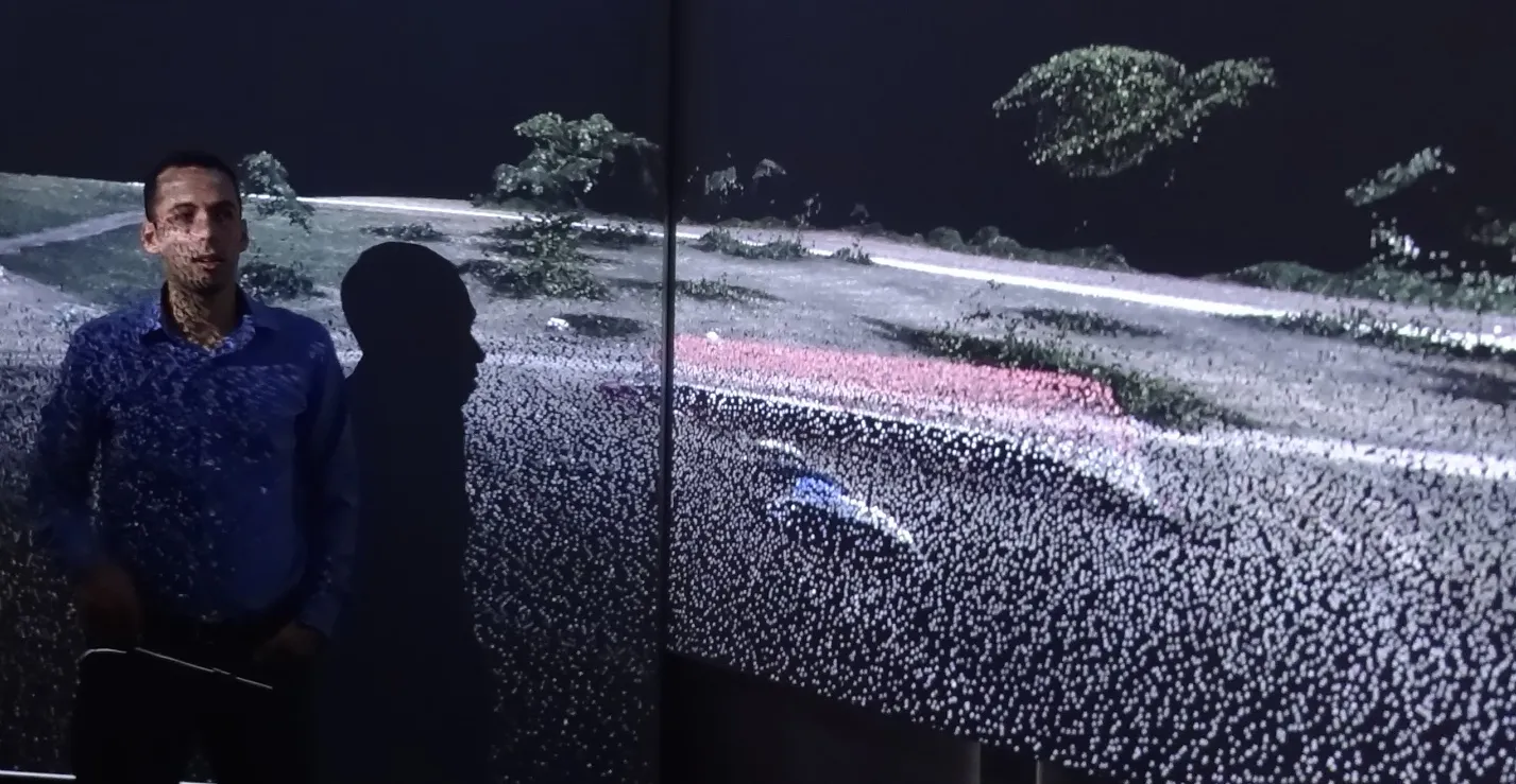
A person standing in front of a wall-sized projection of a UAS point cloud of the Mid Pines fields: a road, scattered trees, and a red-roofed building rendered as thousands of colored dots

UAS SfM point cloud of Mid Pines on the Hunt Library visualization wall.

Lidar acquisition
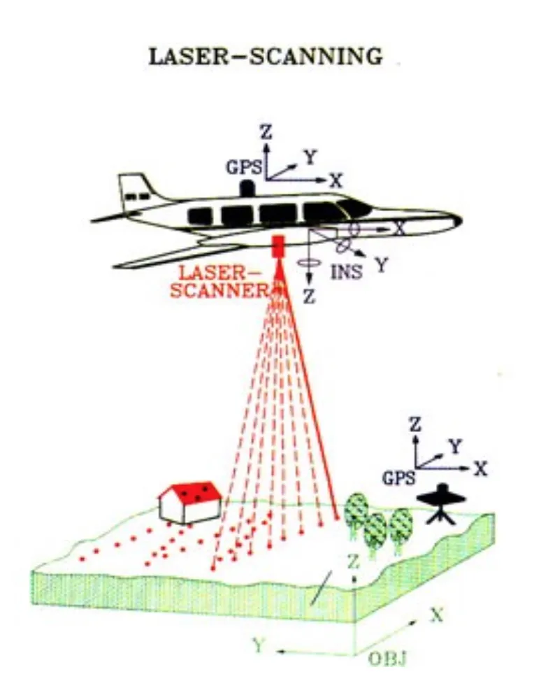
Diagram of airborne laser scanning: an aircraft with a GPS antenna and an INS sends a fan of laser pulses to the ground, where a building, trees, and a GPS base station are drawn on the terrain block

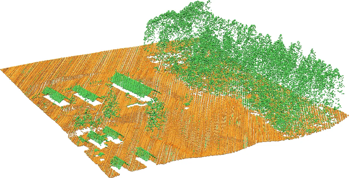
3D view of a lidar point cloud over a field and forest edge: ground points in orange in dense parallel scan lines, trees and roofs in green above them

  • The measured time of flight of each pulse is converted to a distance
  • Georeferencing comes from the platform’s position (GNSS) and orientation (IMU), fused in the INS

Multiple returns
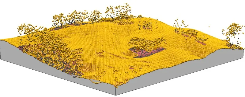
3D view of a lidar point cloud: a dense yellow carpet of first returns over the terrain with tree crowns rising above it, and dark brown second returns visible under the canopy at the forest edges

A lidar pulse can penetrate the tree canopy and produce several returns: yellow first returns, dark brown second returns.

Returns in profile
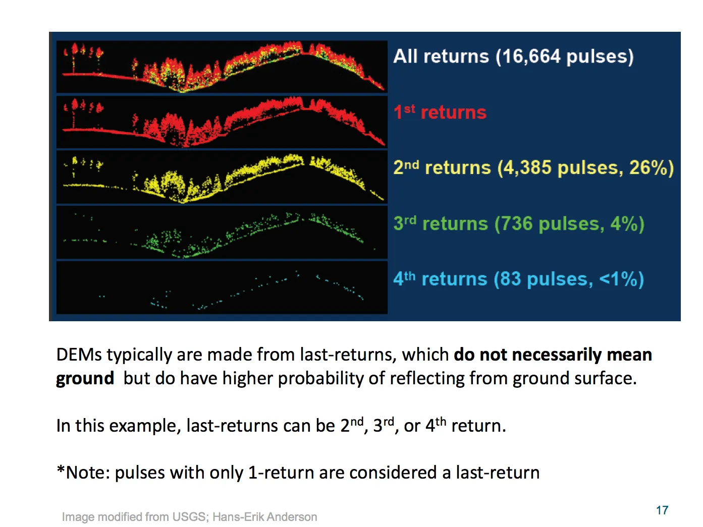
Five stacked profile views of the same forested hill: all returns from 16,664 pulses, then first returns in red, second returns in yellow (26 percent of pulses), third in green (4 percent), and fourth in blue (under 1 percent); a caption notes that DEMs are typically made from last returns, which do not necessarily mean ground

Lidar points

Lidar point: [x, y, z, r, i, c, …], a georeferenced position with the return number r, the intensity i of the echo, and a class c assigned by the provider

  • Additional attributes depend on the sensor and the provider: RGB from a camera, scan angle and direction, GPS time, number of returns per pulse
  • Classes follow the ASPRS LAS standard: 1 unclassified, 2 ground, 7 noise, 9 water, and so on

Lidar preview: swath overlap

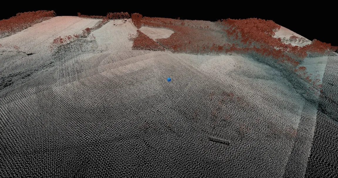
3D view of the Mid Pines lidar point cloud over the fields: regular scan lines across bare fields, trees along the field edges in reddish brown, and a visibly denser band where two flight swaths overlap

Lidar preview: canopy and walls
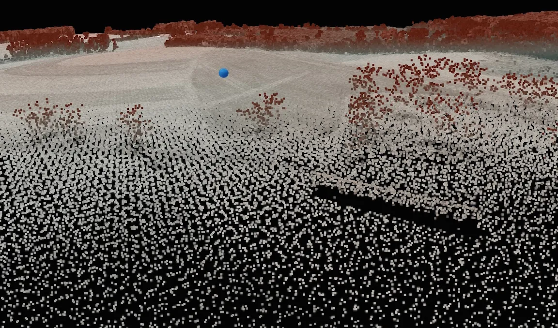
Close-up 3D view of the Mid Pines lidar cloud: points scattered through the tree crowns, the ground visible beneath them, and a building reduced to a flat roof with no points on its walls
  • Points distributed throughout the canopy
  • No points on the walls of the building

SfM points

SfM point: [x, y, z, R, G, B], a position reconstructed from overlapping imagery with the color sampled from the photos

  • No returns, no intensity: the camera sees one surface, the first one in view
  • Classes only if a later step assigns them (Metashape and WebODM can classify ground points)
  • Density depends on the GSD, the overlap, and the quality setting used in dense matching

UAS SfM preview

3D view of the Mid Pines UAS SfM point cloud: a dense carpet of points over bare fields and a road, tree crowns as solid reddish blobs, and a long building fully outlined including its walls
  • Only the top of the tree canopy is captured
  • The building is densely sampled, including the walls

UAS SfM preview in color
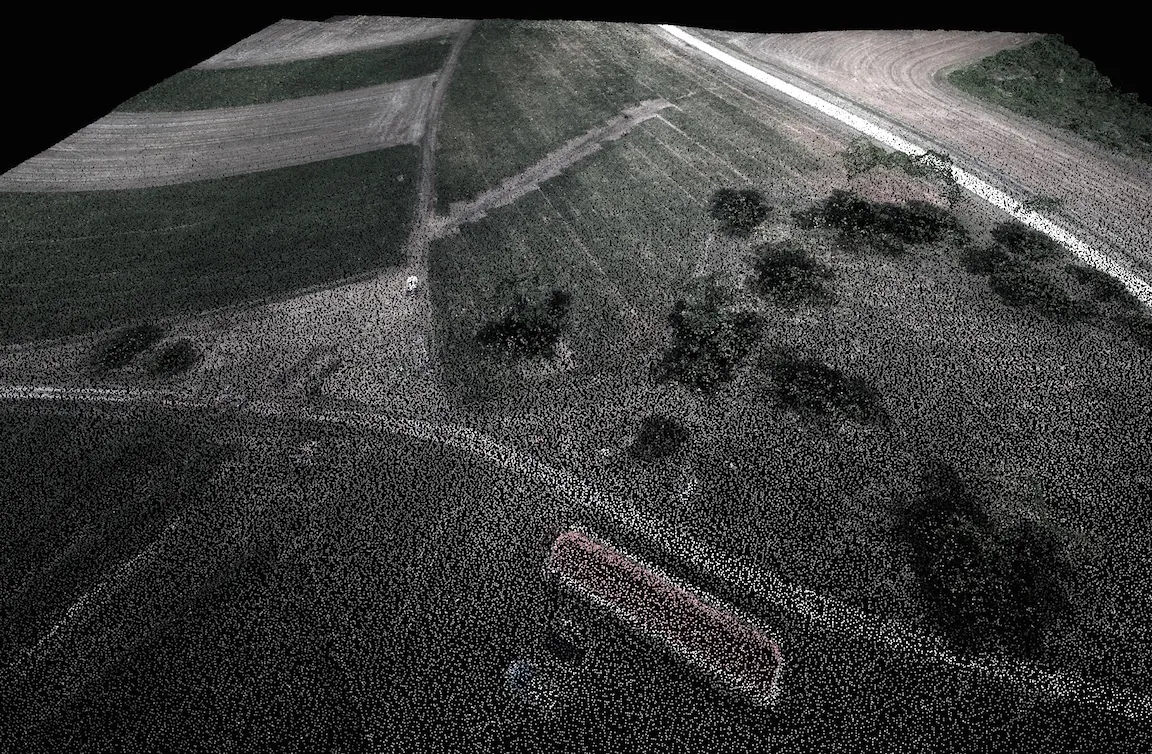
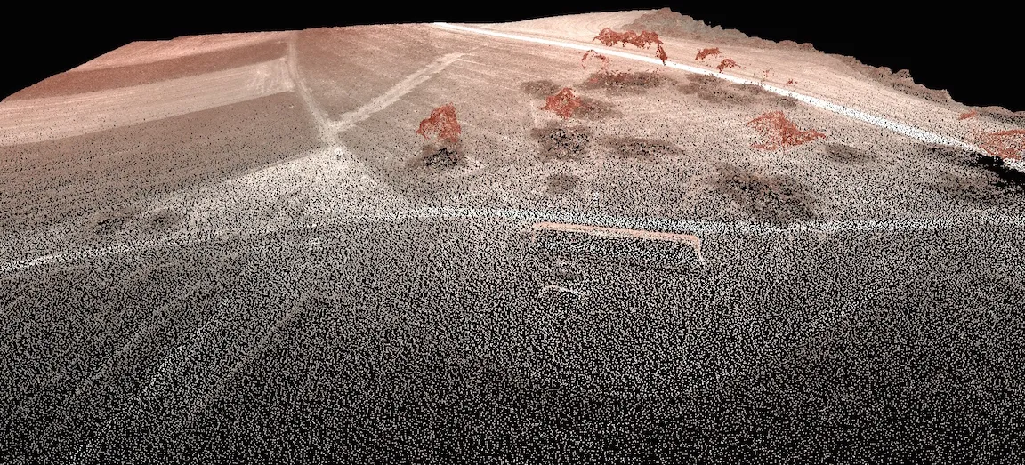
The same Mid Pines UAS point cloud colored by the photos: green crops, a pale dirt road, scattered dark tree crowns, and the red-roofed building, with the density of points visible as grain

Much higher density of points, with RGB from the photos.

Point cloud formats

Format Notes
ASCII x, y, z Oldest and simplest; large, slow, no attributes beyond the columns
LAS Binary industry standard from ASPRS: header, point records with x, y, z, intensity, returns, class
LAZ Losslessly compressed LAS; a fraction of the size, read by most software
COPC Cloud optimized LAZ with a spatial index, streamed straight from a web server

The ASPRS LAS 1.4 specification defines the record and the standard classes; the USGS Lidar Base Specification sets what public lidar must deliver.

Looking at the points

Processing steps

  • Preview, and analyze the point distribution
  • Filter outliers
  • Extract bare earth points
  • Classify: canopy, buildings, and so on
  • Decimate (thin) the cloud
  • Transform the points into surfaces or 3D objects

Binning

Binning: computing a statistic of the points that fall into each cell of a grid at a chosen resolution, with no interpolation; in GRASS, r.in.pdal with method=

  • Number of points per cell: a map of point density
  • Range or standard deviation of z within the cell: a map of vertical variability
  • Shows data gaps and where artifacts will appear
  • The basis for choosing a resolution the data can support

Point density: county lidar

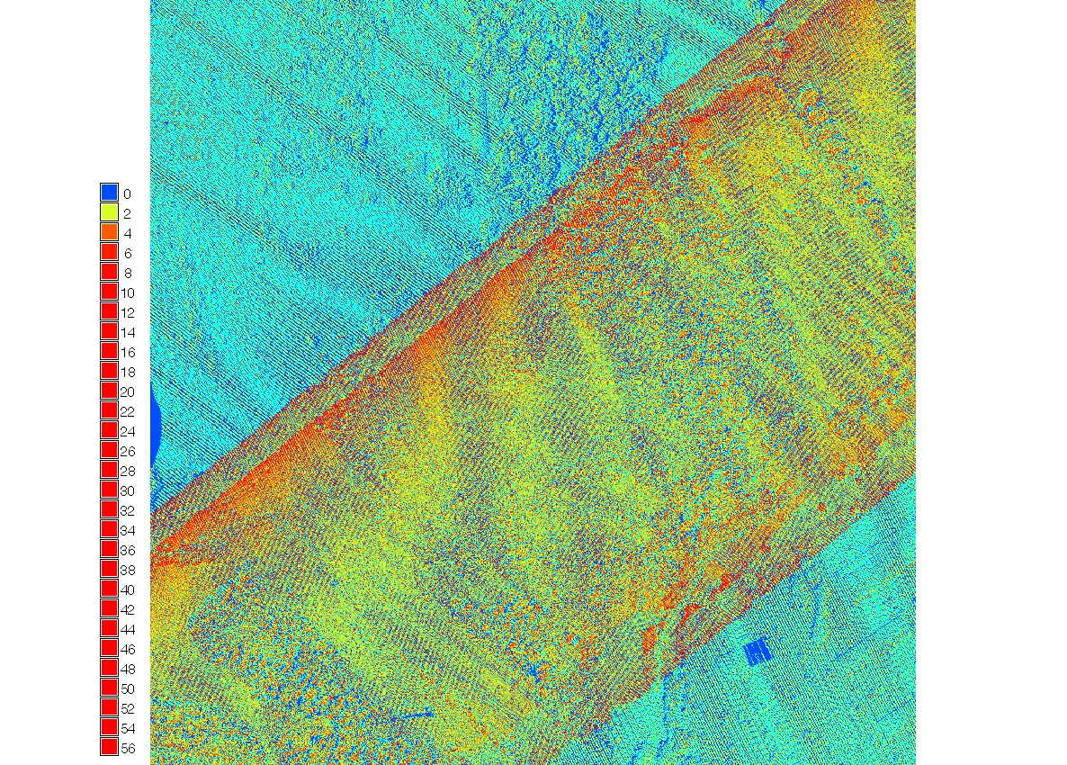
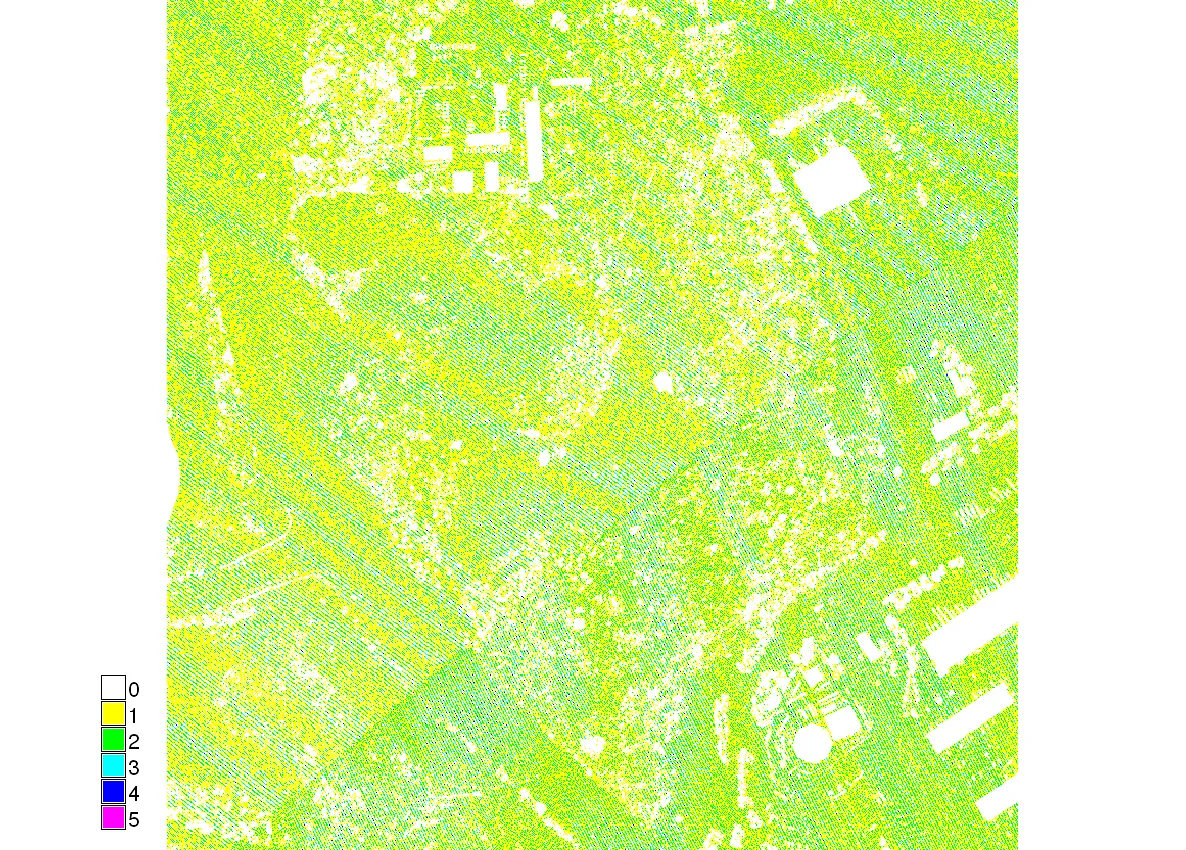
Map of first return point counts per 3 ft cell from the 2013 county lidar: cyan at one to two points over most of the area, with an orange and red diagonal band of four to six points where two swaths overlap

Map of bare earth point counts per 3 ft cell from the same lidar: mostly yellow and green at one to two points, with white gaps of zero points under buildings and tree stands

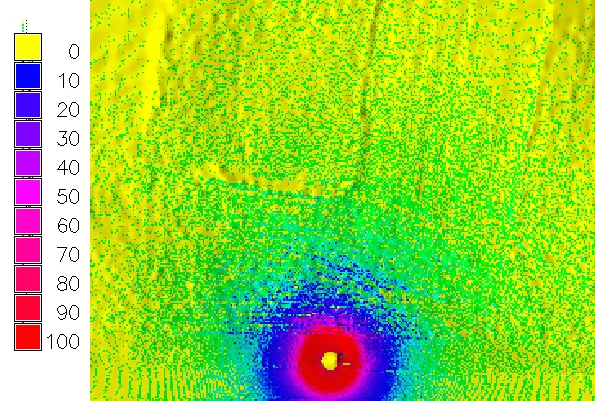
Map of terrestrial lidar point density at 20 cm cells: a red and magenta bullseye of over 100 points near the scanner position fading through blue to yellow near zero at the far edge

All returns and bare earth from the 2013 county lidar, and a terrestrial scan: density rises along swath overlaps and close to a terrestrial scanner.

Point density: Mid Pines lidar
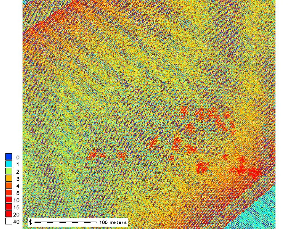
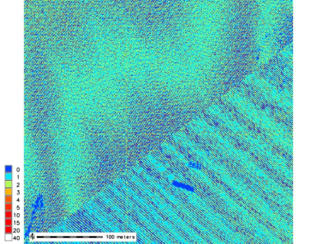
Map of all lidar returns per 1 m cell at Mid Pines: a speckled yellow and orange field of three to five points with diagonal scan stripes, red patches of ten or more points over tree crowns, and a 100 m scale bar

All returns

Map of ground class lidar points per 1 m cell at Mid Pines: mostly cyan at one point with blue zero cells in stripes, and a solid dark blue rectangle with no ground points where a building stands

Ground

Point density: Mid Pines SfM

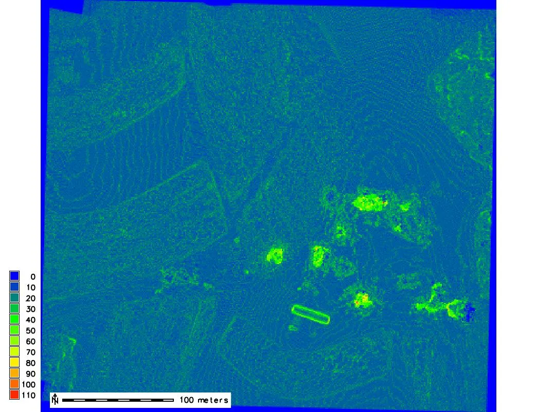
Map of UAS SfM points per 1 m cell at Mid Pines: a fairly even blue field of ten to twenty points with faint contour-like banding, green and yellow patches of fifty or more points on tree crowns and building edges

High point densities around trees and building edges.

Vertical range within a cell
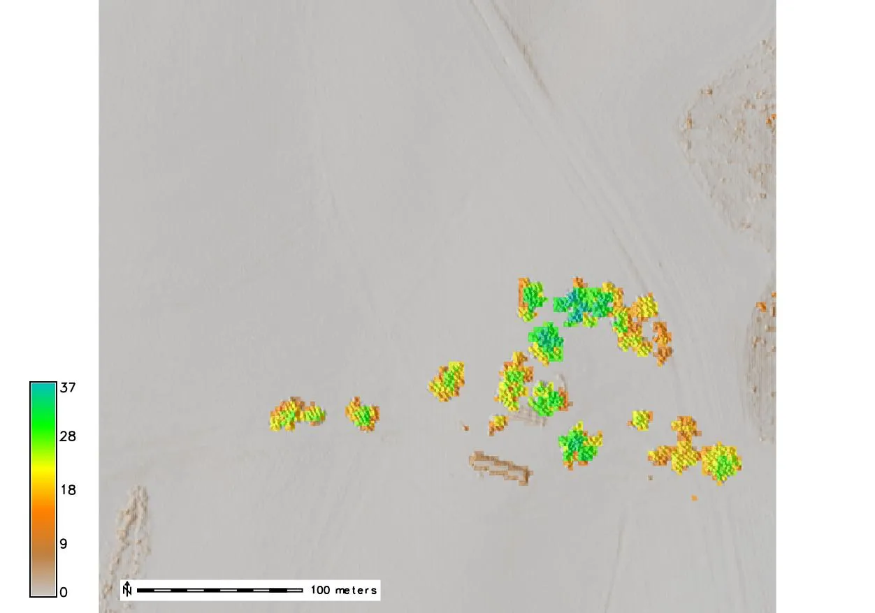
Map of the range of lidar z values per 3 m cell over a shaded relief of Mid Pines: grey near zero on the fields, and tree crowns as patches of green and cyan reaching 28 to 37 m of range

Lidar

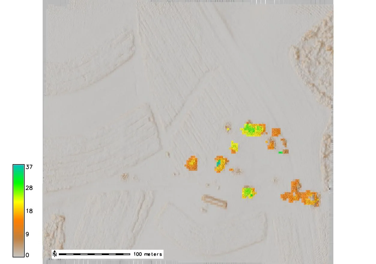
Map of the range of UAS SfM z values per 3 m cell over shaded relief: fields near zero, the same trees as smaller orange and yellow patches of 9 to 28 m of range, and the plowed field pattern visible in the relief

UAS SfM

Lidar reaches through the canopy, so it gives a larger z range and better information about the trees than the denser UAS cloud.

Outliers
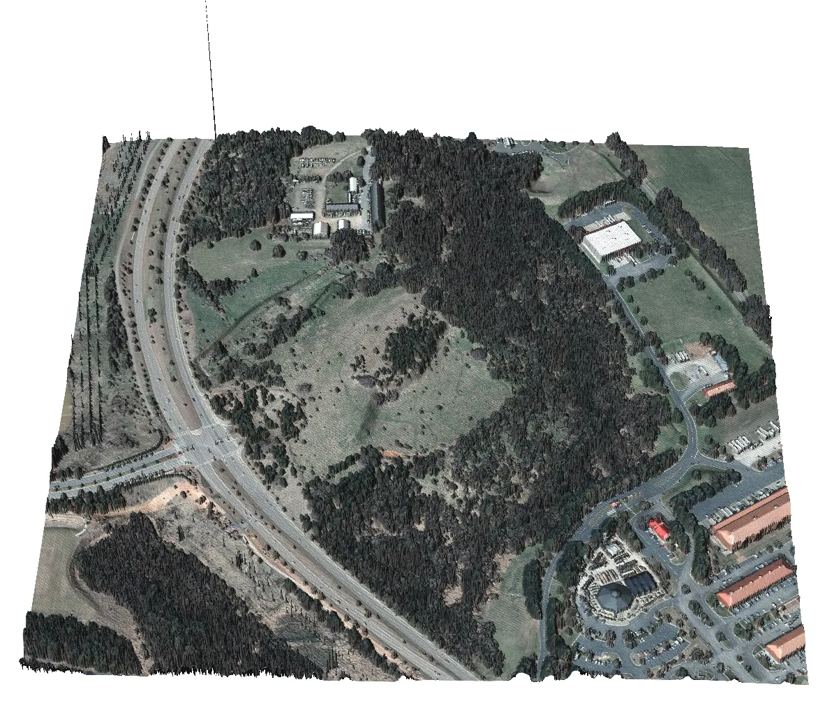
3D view of a binned first return lidar surface over an orthophoto of Centennial Parkway and a wooded campus: trees and buildings stand up correctly, and one thin vertical spike rises far above everything from a single stray point
  • Lidar: birds, airborne particles, reflective materials
  • SfM: errors in point matching
  • Filter with local z-min, z-max, or range thresholds; outliers survive even in processed data

Ground and thinning

Bare ground extraction

Ground classification: labeling the points that lie on the terrain so that a DEM can be built from them alone; the rest is vegetation, buildings, and noise
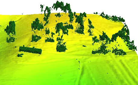
3D view of Mid Pines: a smooth green and yellow ground surface with the lidar points classified as above ground, trees and one long building, standing on it as dark green clusters
  • Multiple returns help but are not required; the surface has to be sampled by enough points
  • Multiscale curvature classification (Evans and Hudak 2007), v.lidar.mcc in GRASS
  • Progressive morphological filter (Zhang et al. 2003)

Decimation

  • Thinning the cloud by subsampling, to make the data manageable
  • The thinning threshold follows from the features that must be preserved
  • Count based: keep every n-th point; preserves variations in density
  • Grid based: keep one point per cell; removes variations in density
  • Distance and geometry based: keep points where the surface changes; more expensive

Decimation: count based

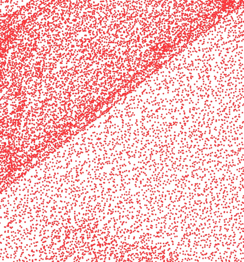
Plan view of a terrestrial lidar point cloud as red dots: very dense in the upper left near the scanner, thinning toward the lower right, with a diagonal ridge of higher density

Full cloud

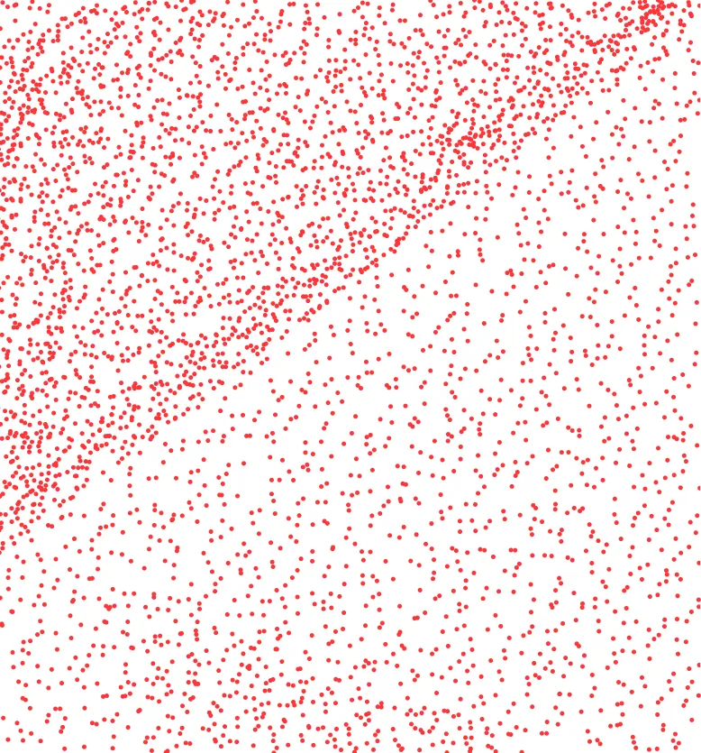
The same cloud keeping every third point: fewer dots everywhere, but the dense upper left and the sparse lower right are still visibly different

Every third point

Preserves the relative point densities.

Decimation: grid based

Plan view of the full terrestrial lidar point cloud as red dots, dense near the scanner and sparse far from it

Full cloud

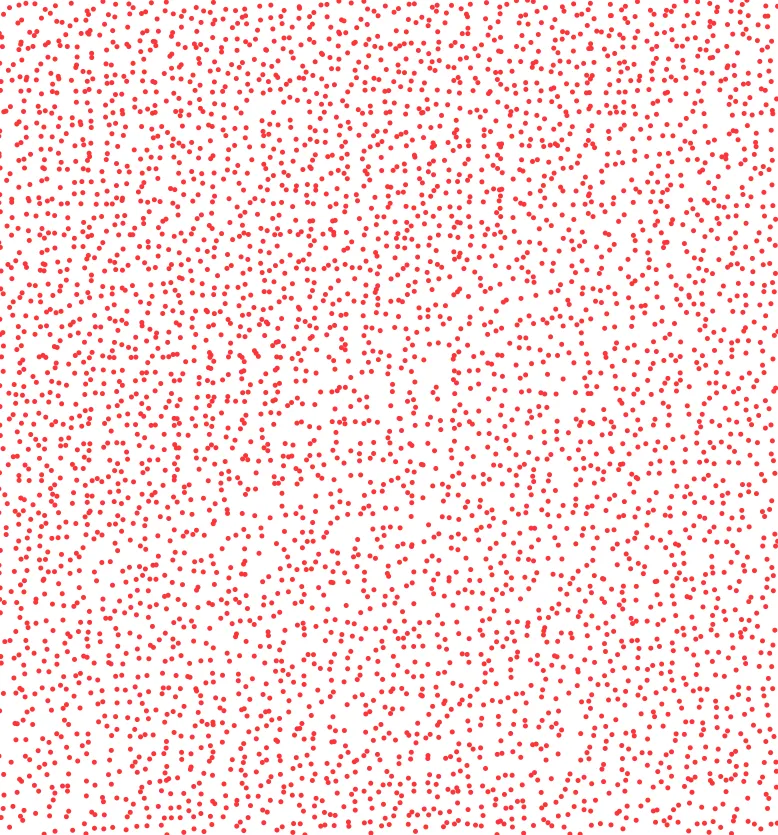
The same cloud thinned to one point per grid cell: an even scatter of red dots across the whole area with no density gradient left

One point per cell

Removes the variations in point density.

From points to surfaces

Three ways to a surface

Method How Strengths Weaknesses
Binning Per cell statistic: mean, min, max, nearest No import, fast, enough for many uses Noisy, no-data cells where points are missing
TIN Triangulate the points into a mesh Variable resolution, standard in 3D design Flat triangles on roads, dams across valleys, few analysis tools, hard to share
Interpolation Fit a surface to the points and sample it on a raster Resolution above the point spacing, smooth, every GIS tool applies Result depends on the method; large rasters

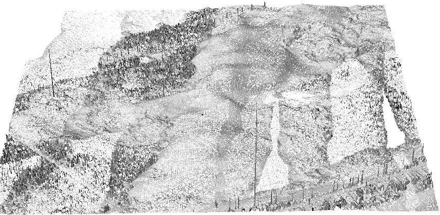
Binning: Jockey’s Ridge 1999 lidar

3D view of a lidar dune field binned at 1 m: the dune shape is visible but the surface is riddled with white holes where cells have no points, and tall spikes stand along one edge

Binned at 1 m: many null cells

3D view of the same dunes binned at 3 m: a continuous grey shaded surface with the dune crests, a few remaining holes at the edges, and rough texture on the vegetated flanks

Binned at 3 m

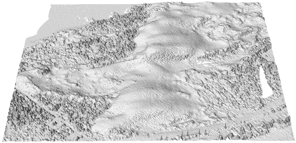
Interpolation: Jockey’s Ridge 1999 lidar
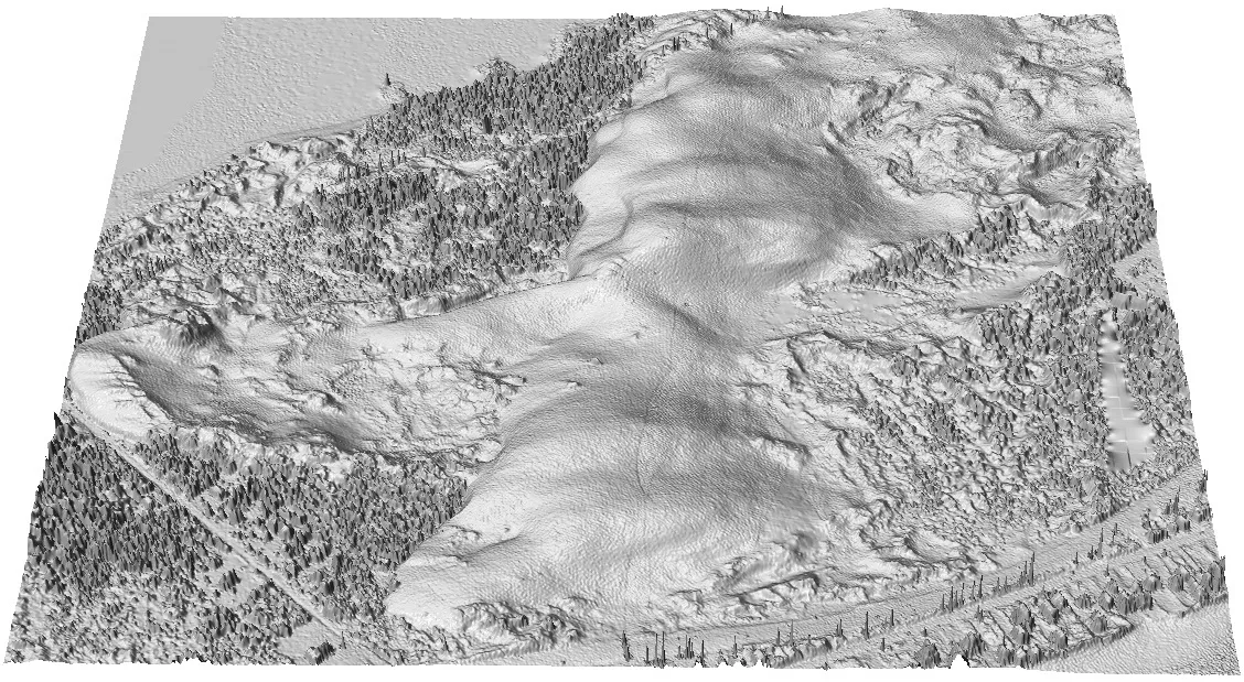
3D shaded view of the Jockey's Ridge dunes interpolated at 1 m: a continuous smooth surface with the dune ridges, slip faces, and vegetation texture, and no holes

Interpolated at 1 m from the same points.

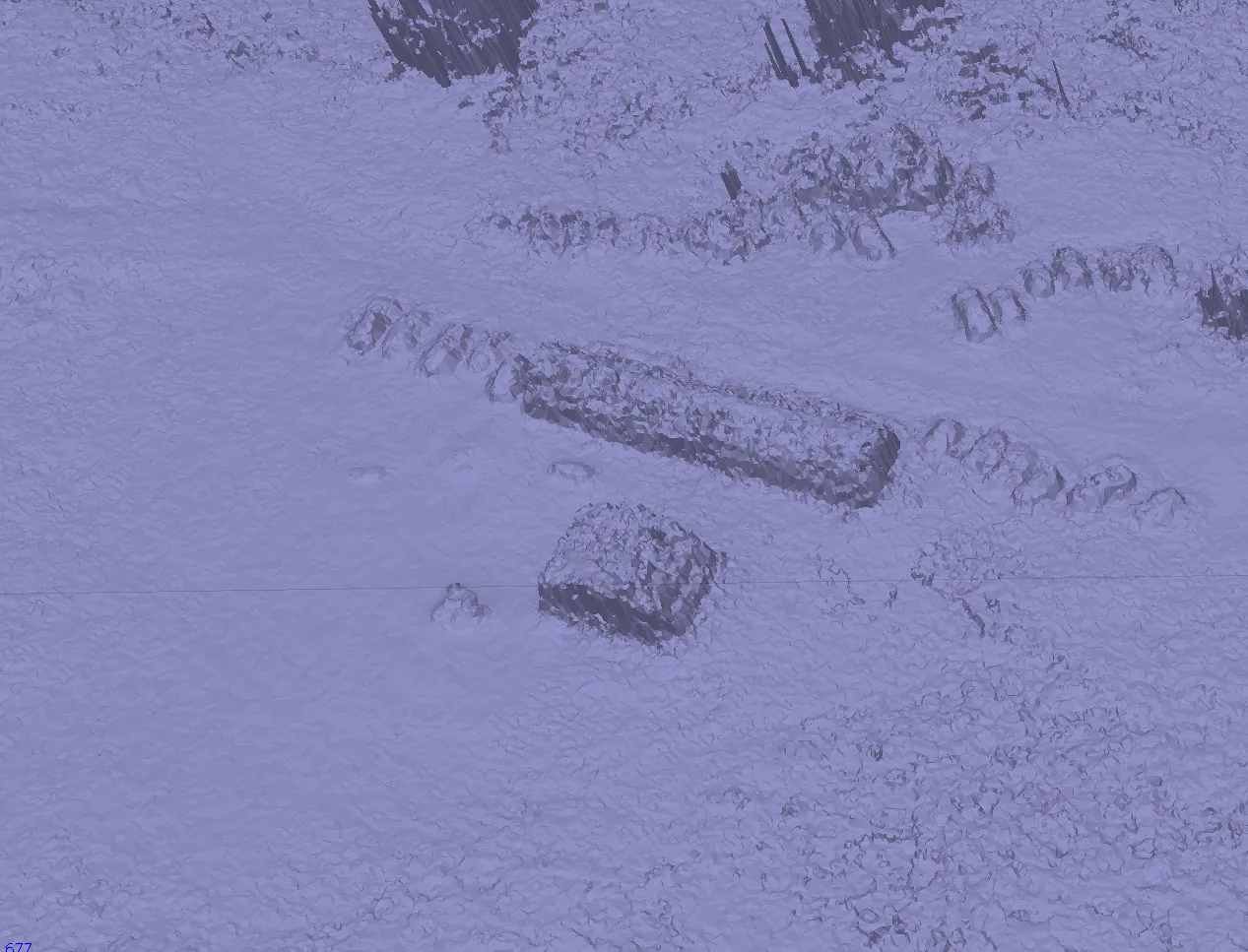
TIN from the Mid Pines SfM cloud
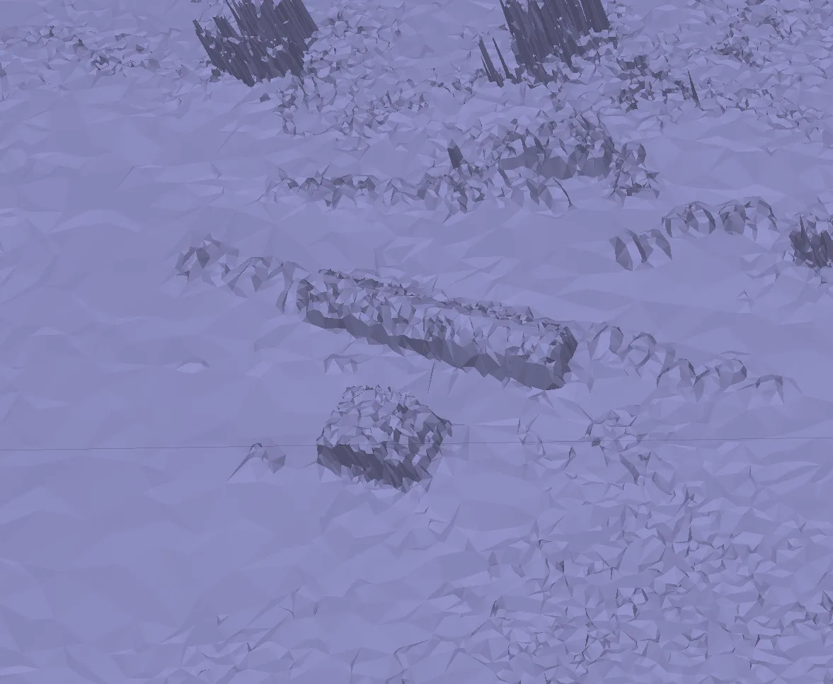
Close-up of a low density triangulated mesh of the Mid Pines SfM cloud in flat blue shading: a long building and a small structure as jagged blocks, trees as clusters of thin spikes, and large flat triangles between

Low density

The same area as a high density mesh: the building and structure have crisp edges, the ground shows fine texture, and the trees are dense spiky clusters

High density

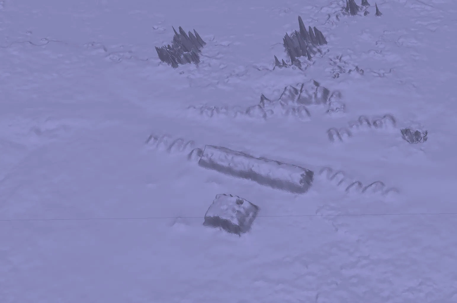
Smoothed TIN

The high density mesh after smoothing: the building and structure as rounded blocks, the ground as a gently undulating surface, and the trees as softened spiky mounds

Interpolated SfM surface

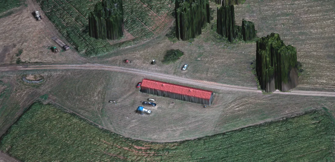
Oblique 3D view of the Mid Pines SfM cloud interpolated by spline and draped with the orthophoto: a long red-roofed building, parked vehicles, a dirt road, and trees that stand up as solid green columns because the surface wraps the crowns

High density SfM point cloud imported to GRASS and interpolated with the regularized spline with tension.

Lidar and SfM DSMs of Mid Pines
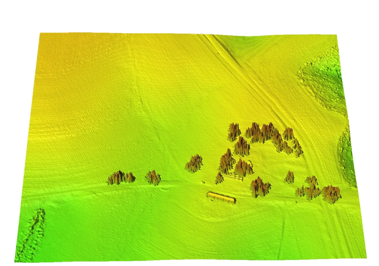
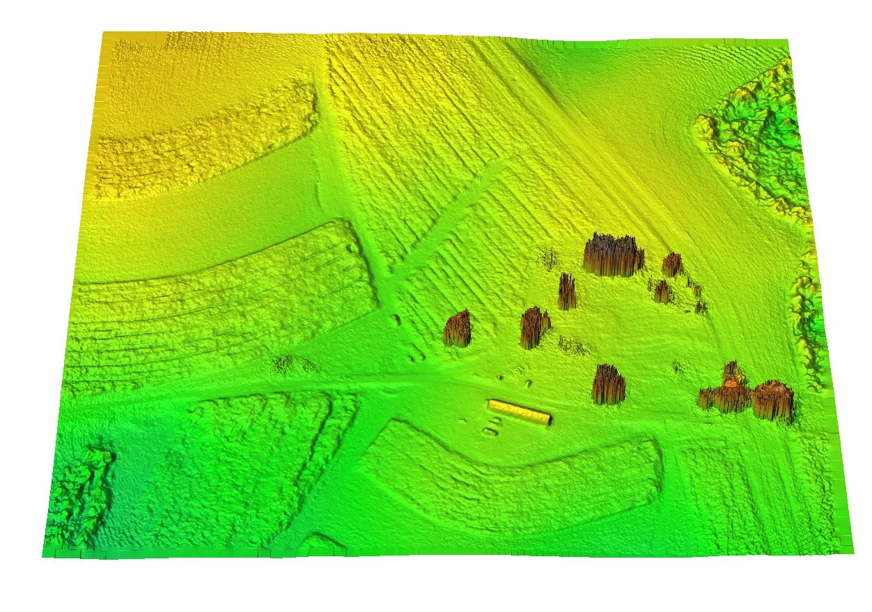
3D view of the interpolated lidar DSM of Mid Pines colored by elevation from green to yellow: smooth fields, a few rows of trees as pointed brown mounds, and the long building as a small block

Lidar

3D view of the interpolated UAS SfM DSM of the same area: the plowed strips and terraces of the fields stand out as fine texture, the trees are dense dark mounds, and the building is sharply outlined

UAS SfM

Topographic analysis

Why derivatives are hard here

  • Point cloud DEMs are noisy, so slope and curvature can reflect the noise or the scan pattern rather than the terrain
  • At high resolution a landform is represented by tens or hundreds of cells, and a 3 x 3 window sees only a fraction of it
  • The result is noisy derivatives, or derivatives biased toward the point distribution

Topographic analysis with splines

  • The regularized spline with tension has explicit equations for its partial derivatives, so slope, aspect, and curvatures are computed in the same run as the interpolation (Mitasova et al. 2005)
  • The parameters come from the original points, tens to hundreds of them per location, not from a 3 x 3 window
  • Tension and smoothing tune the level of detail

In GRASS: v.surf.rst input=points elevation=dem slope=slope aspect=aspect pcurv=pcurv tension=20 smooth=1

Tuning the level of detail

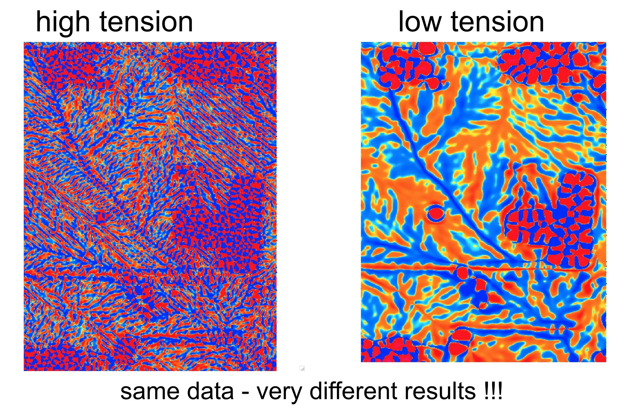
Two profile curvature maps of the same lidar area side by side: with high tension the map is a fine red and blue speckle that follows the scan lines; with low tension it shows branching red and blue valley and ridge patterns with round blobs for the trees; the caption reads same data, very different results

Same points, different tension: high tension follows every point and the scan pattern, low tension shows the landforms.

Curvature and slope on a 1 m DEM

Two 3D views of a 1 m lidar DEM of a stream valley with cultivated terraces: on the left profile curvature in red, blue, and green speckle draped over the terrain; on the right slope in yellow and red, with the terrace faces and the valley sides standing out

Profile curvature and slope draped over the 1 m DEM.

Vertical structure

Voxel models

Voxel model: a 3D raster whose cells hold a statistic of the points inside each volume element, for example the point count; in GRASS, r3.in.xyz after setting a 3D region
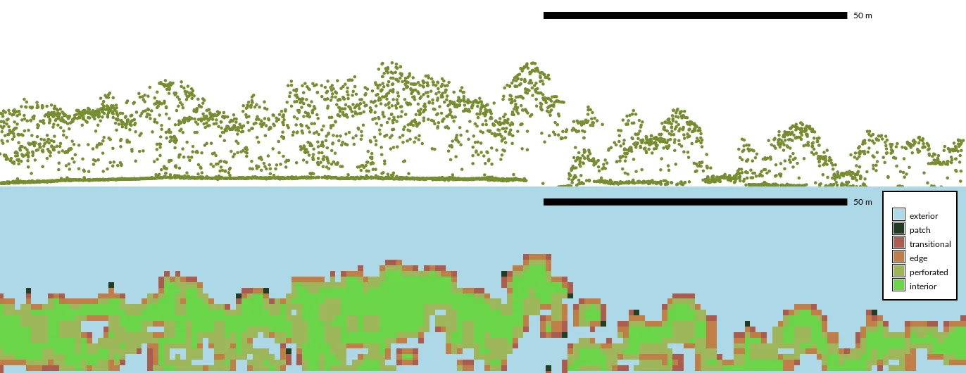
Top: a side profile of lidar points through a forest edge in green, showing crown shapes and the ground line, with a 50 m scale bar. Bottom: the same profile as a classified voxel slice, with interior canopy in green, edge and transitional cells in orange and red, and exterior in light blue

Vertical profile through the point cloud, and the same profile as voxels classified by a 3D fragmentation index.

Voxel cross sections in 3D
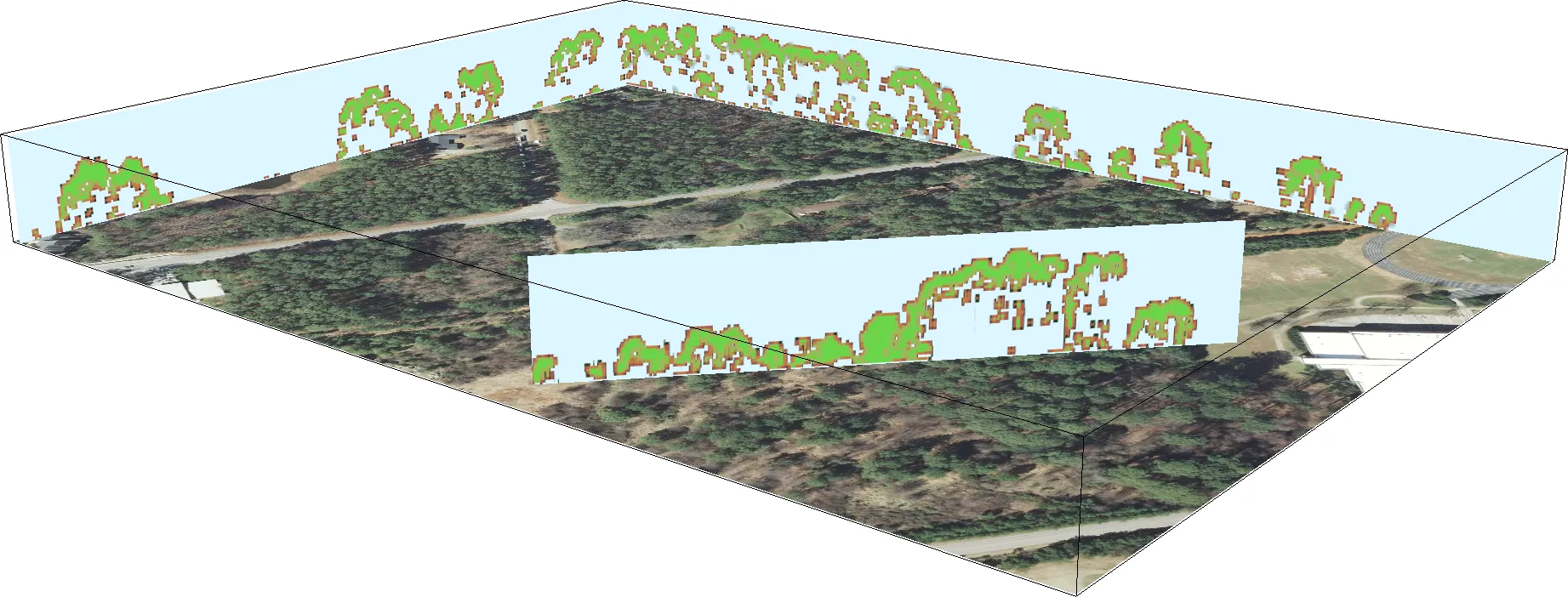
3D view of a forest orthophoto with two vertical slices of a voxel model standing on it, along the far edge and across the middle, each slice showing the canopy as green cells with orange edge cells against a pale blue background

Full waveform lidar

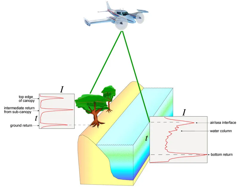
Diagram of an aircraft sending a laser pulse over trees and a coastal water block; two inset graphs of intensity against time show the full returned waveform, with peaks for the top of canopy, sub-canopy, and ground on land, and for the sea surface, water column, and bottom in water

  • A discrete return lidar records a few peaks of the echo; a full waveform system records the entire echo
  • Mammoth Cave National Park: classified point cloud in LAS, raw waveform, and imagery
  • Vertical structure of the canopy from the waveform, not only its top

Mammoth Cave: canopy
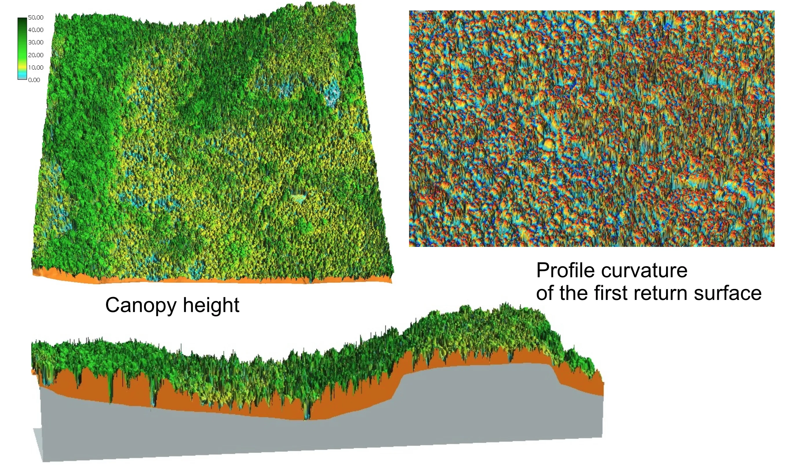
Three panels: a 3D canopy height model of a forested block colored green with a 0 to 50 m legend; a profile curvature map of the first return surface as dense red and blue speckle; and a cross section showing the canopy in green above the orange ground surface and grey bedrock block

Mammoth Cave: bare earth

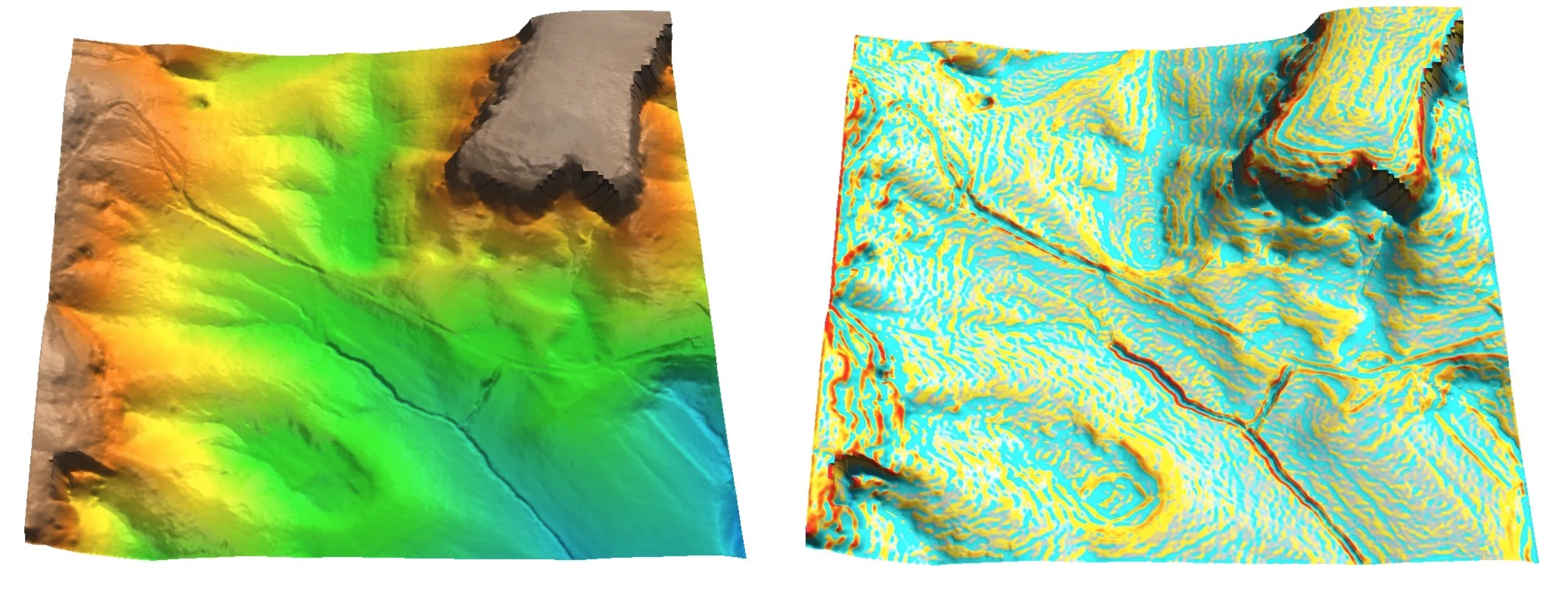
Two 3D views of the Mammoth Cave bare earth DEM: on the left colored by elevation from blue valleys through green to orange and brown ridges, with a flat-topped plateau in one corner; on the right profile curvature in cyan and yellow with red along the sharp breaks of the plateau edge and the stream channels

Voxel models of canopy density

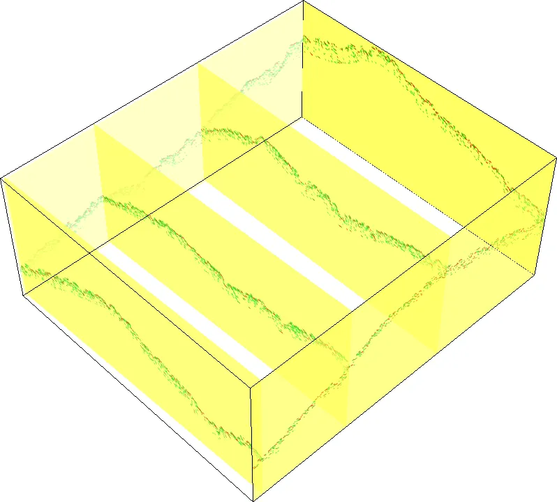
A translucent yellow 3D box with four vertical slices through it, each slice showing a wavy green and red line where the canopy surface cuts the slice

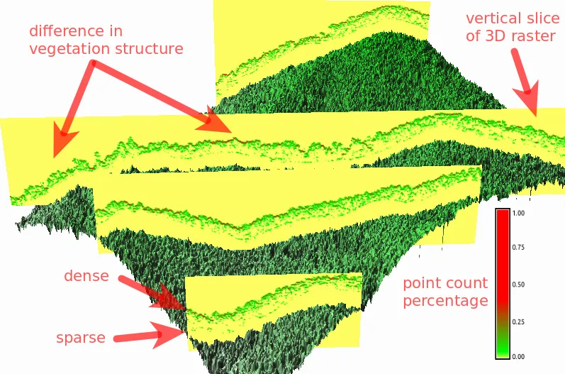
3D view of forested terrain with vertical yellow slices of a voxel model showing the canopy as a band colored from green for sparse to red for dense point count percentage; arrows mark a difference in vegetation structure between two stands and label dense and sparse canopy

Point count per voxel as a percentage, sliced through two forest stands with different structure (Petras et al. 2016).

Lidar today

Airborne lidar today

  • Manned aircraft carry the newest sensors: full waveform, multispectral, and single photon lidar
  • Single photon lidar detects one photon per return, so it maps terrain and forest structure over whole counties from high altitude in a few flights (Swatantran et al. 2016)
  • Against full waveform lidar it needs fewer passes for the same density, but the cloud is noisier and needs more filtering (Mandlburger et al. 2019)
  • Geiger mode lidar is the other photon counting design: each detector pixel records one photon per pulse, so the cloud is built from thousands of overlapping looks (Stoker et al. 2016)

UAS lidar today

  • Small spinning and solid state scanners made UAS lidar routine
    • a DJI Zenmuse L2 on a Matrice 350 maps a field at several hundred points per square meter
  • Discrete return, a few returns per pulse, like the 2013 cloud in the lab
  • Accuracy still rests on the GNSS and IMU of the platform

Public lidar data sources

Source What you get
USGS 3DEP Nationwide point clouds streamed as Entwine tiles, plus DEMs through The National Map
NOAA Digital Coast Coastal point clouds with on the fly binning and download
NC OneMap The statewide QL2 lidar flown 2014 to 2017: points, DEMs, and derived products
OpenTopography Research lidar (NCALM and others) with on demand DEM generation

More on lidar in GRASS at the GRASS wiki, and a full workshop at Processing lidar and UAV point clouds in GRASS.

Key terms

Return: one echo of a lidar pulse; a pulse through a canopy gives several, the last one most likely from the ground

Class: the label a provider or an algorithm assigned to a point: ground, unclassified, noise, water

Binning: a per cell statistic of the points, with no interpolation

Interpolation: a surface fitted to the points and sampled on a raster, at a resolution the point spacing can support

DEM vs DSM: ground points give the terrain; first returns or all points give the surface, canopy and roofs included

Voxel model: a 3D raster of point statistics, keeping the vertical structure a DSM throws away

Wrap-up

Assignment 4B: Processing lidar and UAS SfM point clouds: bin and compare the densities of the two Mid Pines clouds, classify by returns, interpolate a DEM and DSM with their derivatives, and validate the lidar DEM against the surveyed GCPs

References

Evans, Jeffrey S., and Andrew T. Hudak. 2007. “A Multiscale Curvature Algorithm for Classifying Discrete Return LiDAR in Forested Environments.” IEEE Transactions on Geoscience and Remote Sensing 45 (4): 1029–38. https://doi.org/10.1109/TGRS.2006.890412.
Mandlburger, Gottfried, Harald Lehner, and Norbert Pfeifer. 2019. “A Comparison of Single Photon and Full Waveform Lidar.” ISPRS Annals of the Photogrammetry, Remote Sensing and Spatial Information Sciences IV-2/W5: 397–404. https://doi.org/10.5194/isprs-annals-IV-2-W5-397-2019.
Mitasova, Helena, Lubos Mitas, and Russell S. Harmon. 2005. “Simultaneous Spline Approximation and Topographic Analysis for Lidar Elevation Data in Open-Source GIS.” IEEE Geoscience and Remote Sensing Letters 2 (4): 375–79. https://doi.org/10.1109/LGRS.2005.848533.
Petras, Vaclav, Anna Petrasova, Justyna Jeziorska, and Helena Mitasova. 2016. “Processing UAV and Lidar Point Clouds in GRASS GIS.” The International Archives of the Photogrammetry, Remote Sensing and Spatial Information Sciences XLI-B7: 945–52. https://doi.org/10.5194/isprs-archives-XLI-B7-945-2016.
Stoker, Jason, Qassim Abdullah, Amar Nayegandhi, and Jayna Winehouse. 2016. “Evaluation of Single Photon and Geiger Mode Lidar for the 3D Elevation Program.” Remote Sensing 8 (9): 767. https://doi.org/10.3390/rs8090767.
Swatantran, Anu, Hao Tang, Terence Barrett, Phil DeCola, and Ralph Dubayah. 2016. “Rapid, High-Resolution Forest Structure and Terrain Mapping over Large Areas Using Single Photon Lidar.” Scientific Reports 6: 28277. https://doi.org/10.1038/srep28277.
Zhang, Keqi, Shu-Ching Chen, Dean Whitman, Mei-Ling Shyu, Jianhua Yan, and Chengcui Zhang. 2003. “A Progressive Morphological Filter for Removing Nonground Measurements from Airborne LIDAR Data.” IEEE Transactions on Geoscience and Remote Sensing 41 (4): 872–82. https://doi.org/10.1109/TGRS.2003.810682.