Imagery processing - Agisoft PhotoScan Professional
UAS Operations and Analytics Workshop
Software capabilities
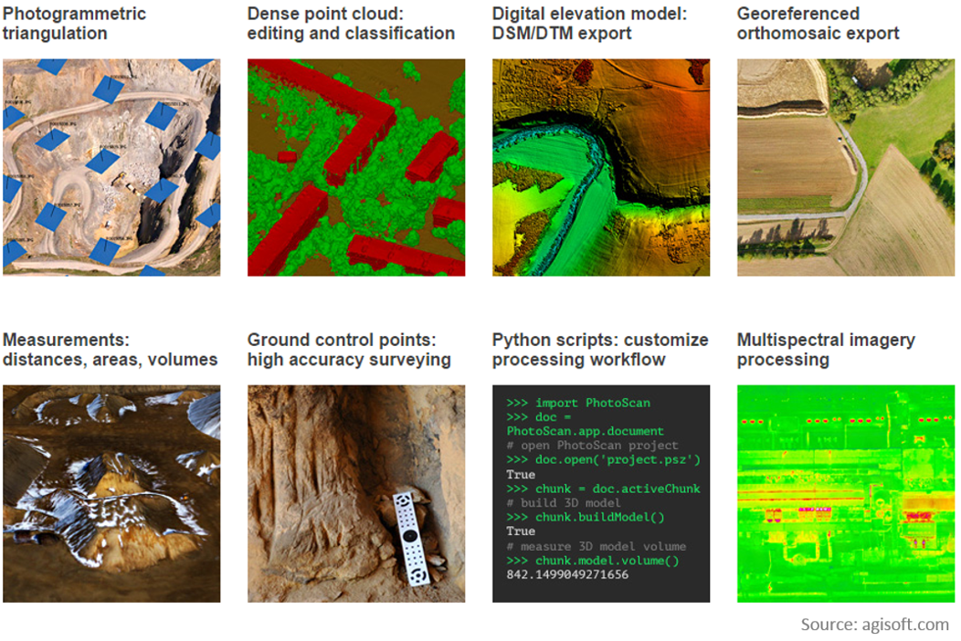
Agisoft PhotoScan Professional
- Image-based solution aimed at creating 3D content from still images;
- Operates with arbitrary images and is efficient in both controlled and uncontrolled conditions;
- Both image alignment and 3D model reconstruction are fully automated.
Processing workflow
see the detailed step-by-step tutorial ;

Preprocessing stage:

- loading photos into PhotoScan;
- inspecting loaded images, removing unnecessary images.
Processing workflow
Processing stage:

- Aligning photos;
- Building dense point cloud;
(optional: editing dense point cloud)
- Building mesh (3D polygonal model);
(optional: editing mesh)
- Generating texture;
- Building DSM and orthomosaic
Processing workflow
Exporting results

Preprocessing
- Loading photos,
- Loading camera positions (flight log)
- If the EO is in the photos EXIF file, the parameters will load automatically
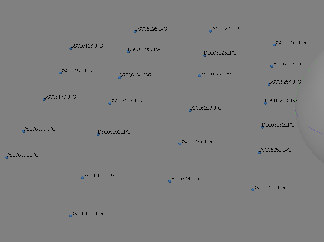
1. Aligning photos
At this stage Agisoft PhotoScan:
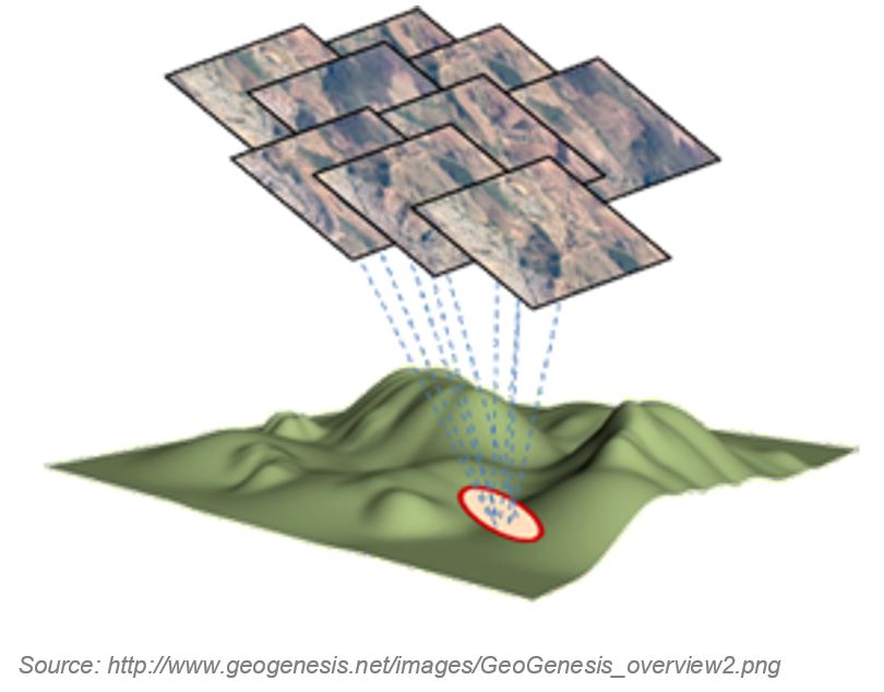
implements SfM algorithms to monitor the movement of features through sequence of multiple images:
- obtains the relative location of the acquisition positions,
- refines camera calibration parameters,
- sparse point cloud and a set of camera positions are formed.
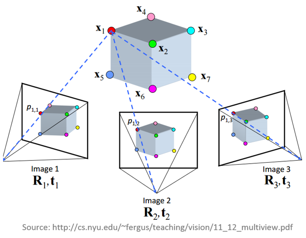
Bundle Block Adjustment
- Non-linear method for refining structure and motion
- Minimizing reprojection error
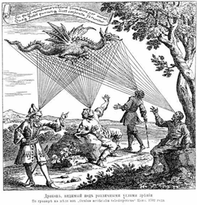
- Detecting image feature points (i.e. Various geometrical similarities such as object edges or other specific details);
Bundle Block Adjustment
- Subsequently monitoring the movement of those points throughout the sequence of multiple images;
- Using this information as input, the locations of those feature points can be estimated and rendered as a sparse 3D point cloud
Aligning cameras in PhotoScan
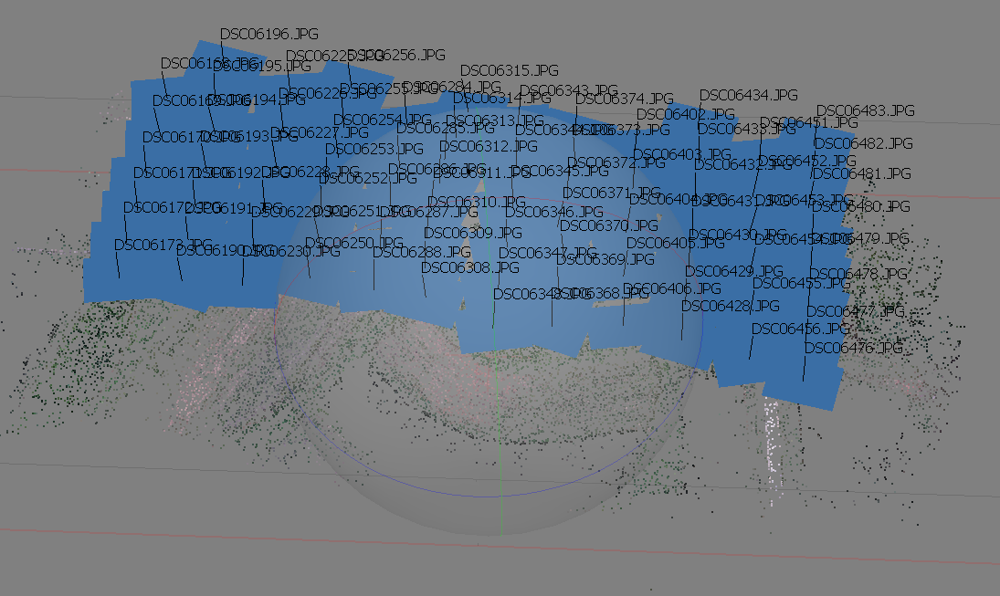
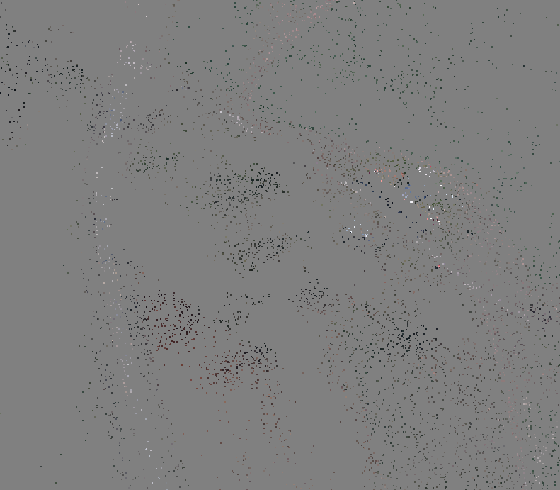
sparse point cloud generation
Accuracy
- High accuracy setting > more accurate camera position estimates (time consuming);
- Low accuracy setting > rough camera positions.
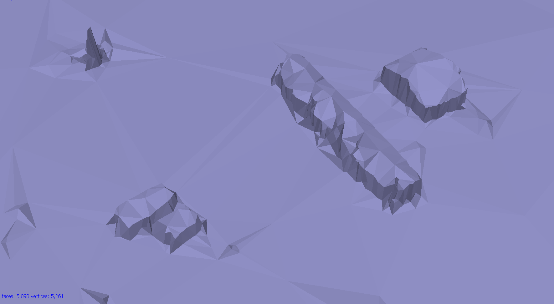
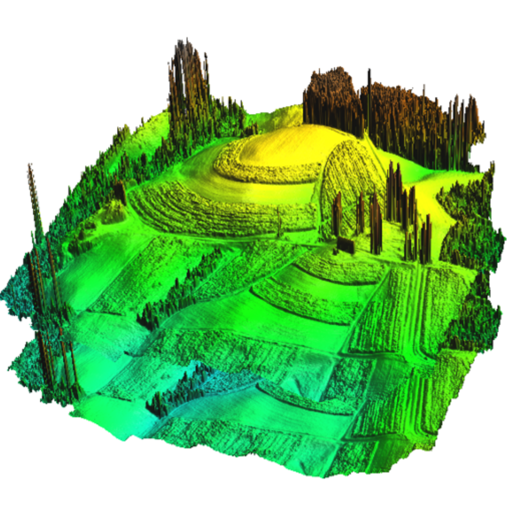
2. Building dense point cloud
At the stage of dense point cloud generation reconstruction PhotoScan calculates depth maps for every image
- Quality: Highest, High, Medium, Low, Lower> the higher quality the more accurate camera position estimates but the process is more time consuming

2. Building dense point cloud
Depth Filtering modes
Algorithms sorting outliers
(due to some factors, like poor texture of some elements of the scene, noisy or badly focused images)
- Mild depth filtering mode > for complex geometry (numerous small details on the foreground), for important features not to be sorted out;
- Aggressive depth filtering mode > sorting out most of the outliers;
- Moderate depth filtering mode > results in between the Mild and Aggressive
Optional: editing dense point cloud
- Manual points removal
- Automatic filtering based on applied masks;
- Sparse cloud only:
- Reducing number of points in cloud by setting tie point per photo limit
- Automatic filtering based on:
- Reprojection error;
- Reconstruction uncertainty;
- Image count.
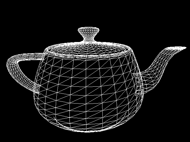
3. Building mesh
- Arbitrary > for modeling of any kind of object
- should be selected for closed objects (statues, buildings, etc.);
- memory consumption: high
- should be selected for aerial photography;
- memory consumption: low
- allows for larger data sets processing.
3. Building mesh
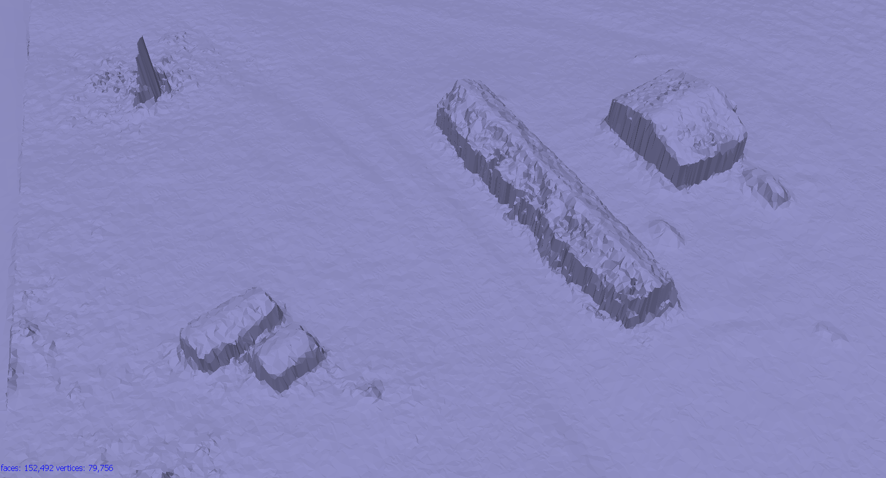
- Source data > the source for the mesh generation
- Sparse cloud > fast 3D model generation (low quailty)
- Dense cloud > high quality output based on the previously reconstructed dense point cloud.
- Face count > the maximum face count in the final mesh.
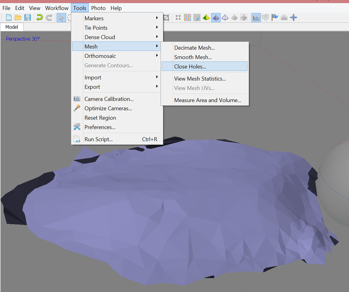
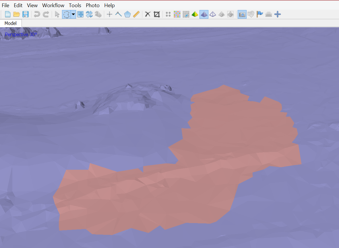
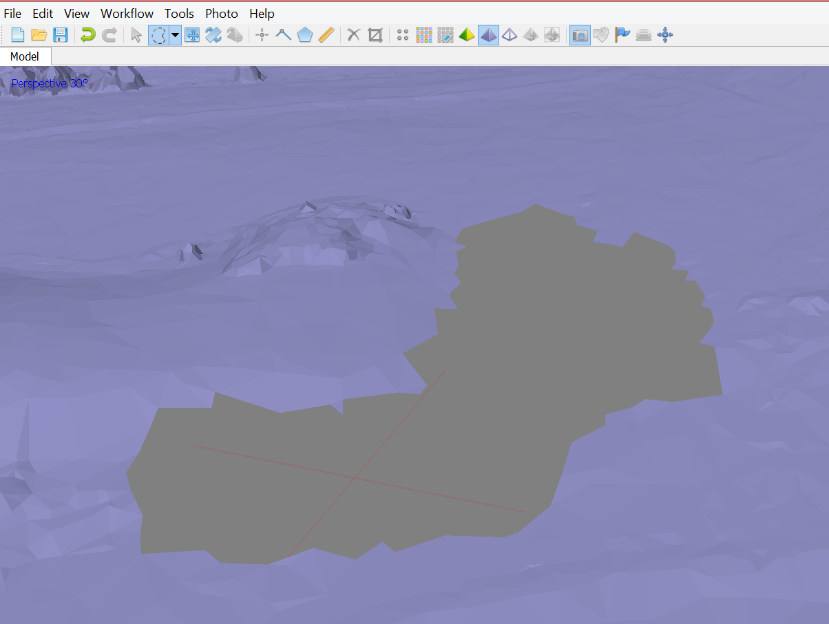
Optional: editing mesh
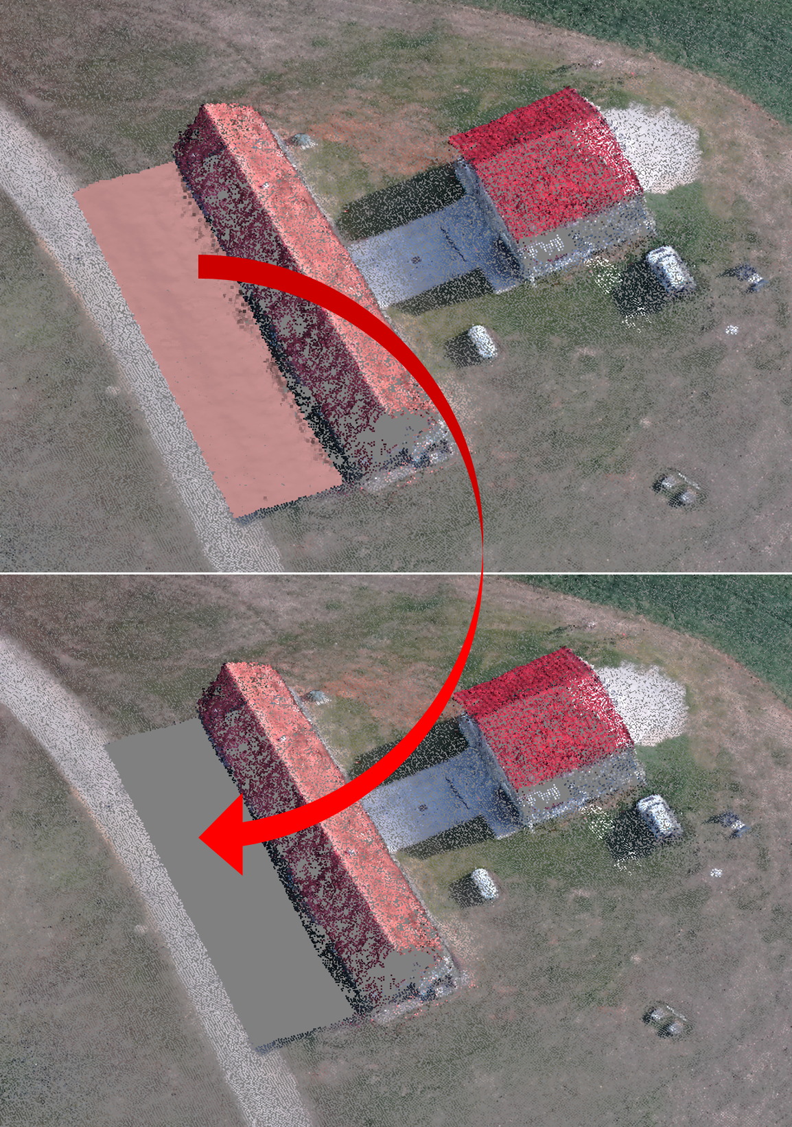
- Close Holes tool > repairs your model if the reconstruction procedure resulted in a mesh with several holes, due to insufficient image overlapnecessary step for volumes calculation;
- Decimation tool > decreases the geometric resolution of the model by replacing high resolution mesh with a lower resolution one;
Optional: editing mesh
- Automatic filtering based on specified criterion:
- Connected component size,
- Polygon size.
- Manual polygon removal,
- Fixing mesh topology,
- Editing mesh in the external program
export mesh for editing in the external program > import edited mesh
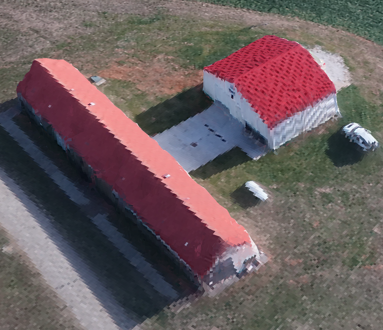
4. Generating texture
- Determines how the object texture will be packed in the texture atlas;
- Effects the quality of the final model;
- Texture mapping modes:
- Generic,
- Adaptive orthophoto,
- Orthophoto,
- Spherical,
- Single photo,
- Keep uv.
4. Generating texture
- Determines how the object texture will be packed in the texture atlas;
- Effects the quality of the final model;
- Texture mapping modes:
- Generic,
- Adaptive orthophoto,
- Orthophoto,
- Spherical,
- Single photo,
- Keep uv.
Texture mapping modes
- Generic
- creates as uniform texture as possible.
- Adaptive orthophoto
- The object surface split into the flat part and vertical regions;
- The flat part of the surface textured using the orthographic projection, while vertical regions textured separately to maintain accurate texture representation in such regions;
- More compact texture representation for nearly planar scenes + good texture quality for vertical surfaces.
Texture mapping modes
- Orthophoto
- The whole object surface textured in the orthographic projection;
- Even more compact texture representation than the Adaptive orthophoto at the expense of texture quality in vertical regions.
- Spherical - Only for objects that have a ball-like form.
- Single photo - Texture from a single photo (photo can be selected from 'Texture from' list)
- Keep uv: Generates texture atlas using current texture parametrization; Rebuilding current texture with different resolution or generating the atlas parametrized in the external software.
Generating DSM
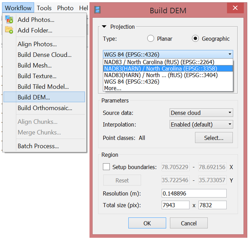
Parameters
- Source data: dense point cloud
- Interpolation
- Disabled: leads to accurate reconstruction results since only areas corresponding to dense point cloud points are reconstructed
- Enabled (recommended): interpolation mode PhotoScan will calculate DEM for all areas of thescene that are visible on at least one image.
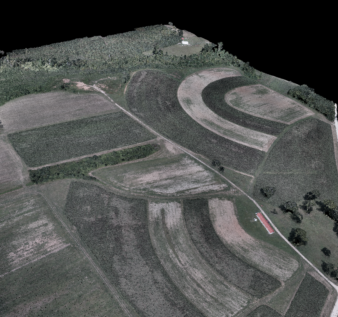
Generating orthophoto
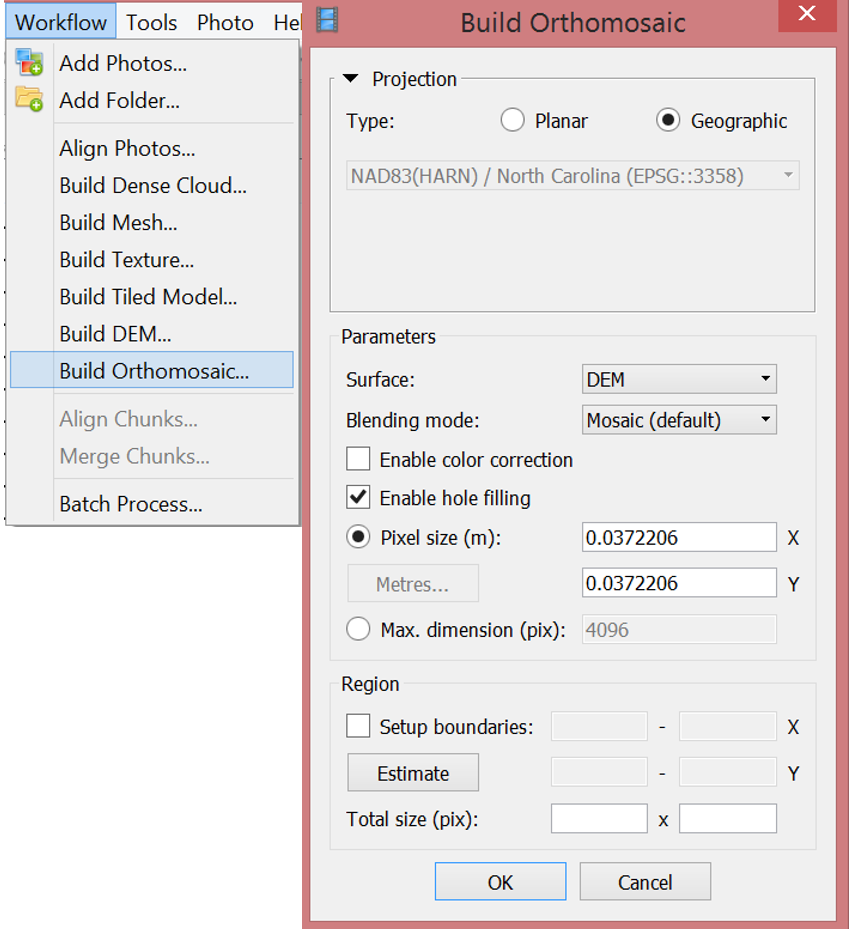
Parameters
- Surface: DEM
- Bleding mode
- Mosaic (default): implements approach with data division into several frequency domains which are blended independently.
- Average: uses the weighted average value of all pixels from individual photos.
- Disabled: the color value for the pixel is taken from the photo with the camera view being almost along the normal to the reconstructed surface in that point.
Exporting results
and saving intermediate results
- Orthophoto export
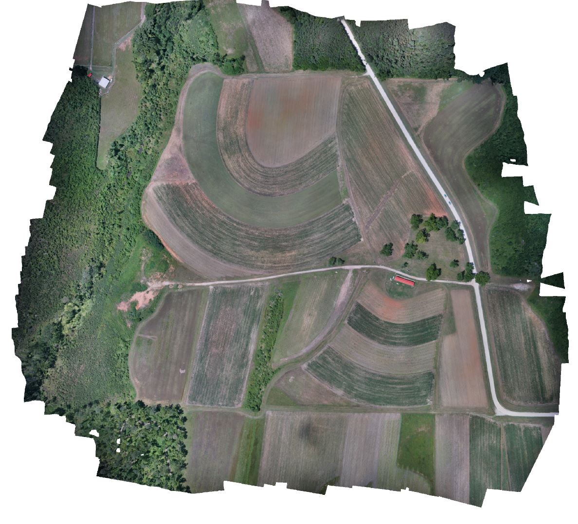
Exporting results
and saving intermediate results
- Orthophoto export
- DEM export
Exporting results
and saving intermediate results
- Orthophoto export
- DEM export
- 3D model export
Exporting results
and saving intermediate results
- Orthophoto export
- DEM export
- 3D model export
- Point cloud export
Exporting results
and saving intermediate results
- Orthophoto export
- DEM export
- 3D model export
- Point cloud export
- Processing report generation
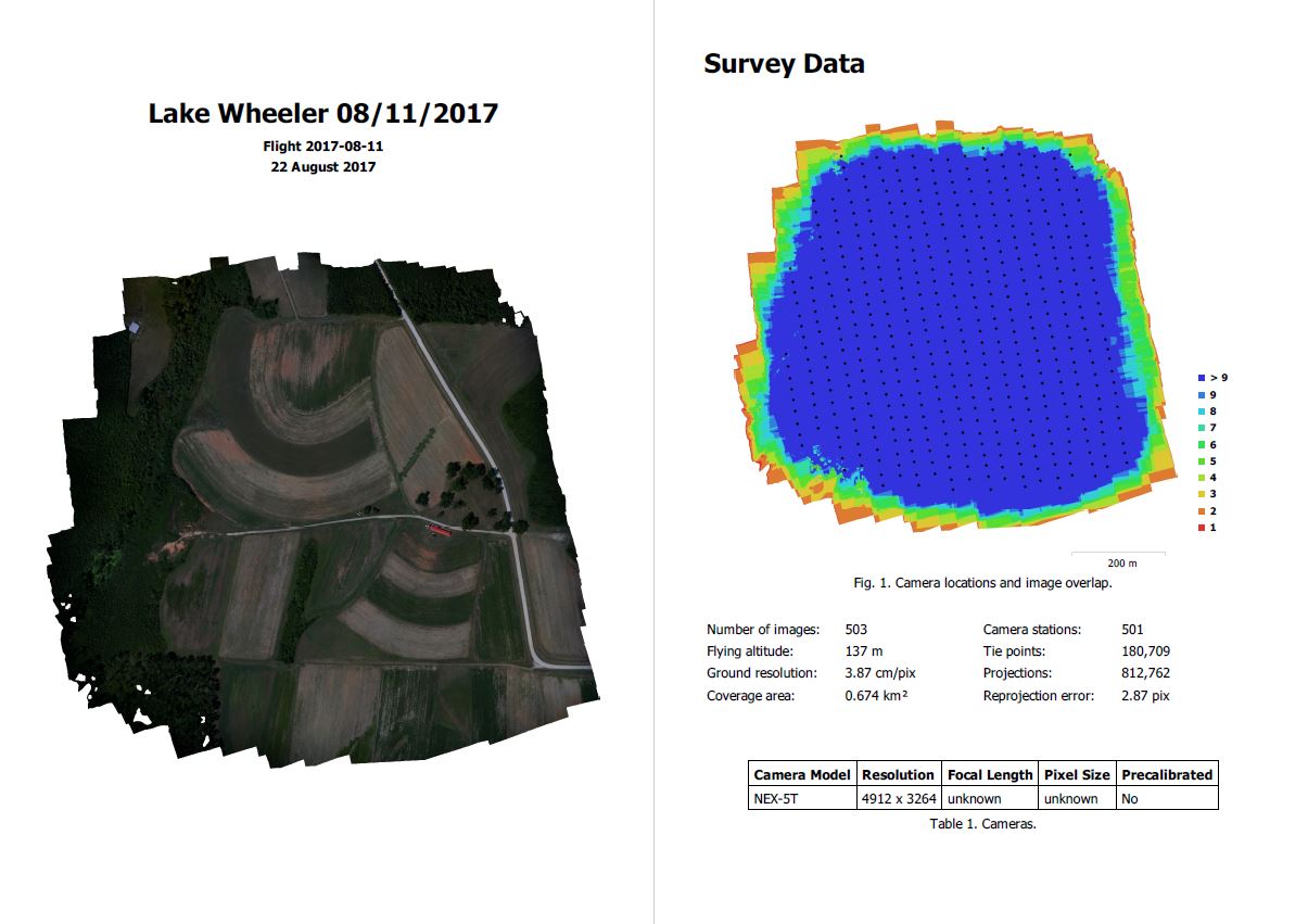
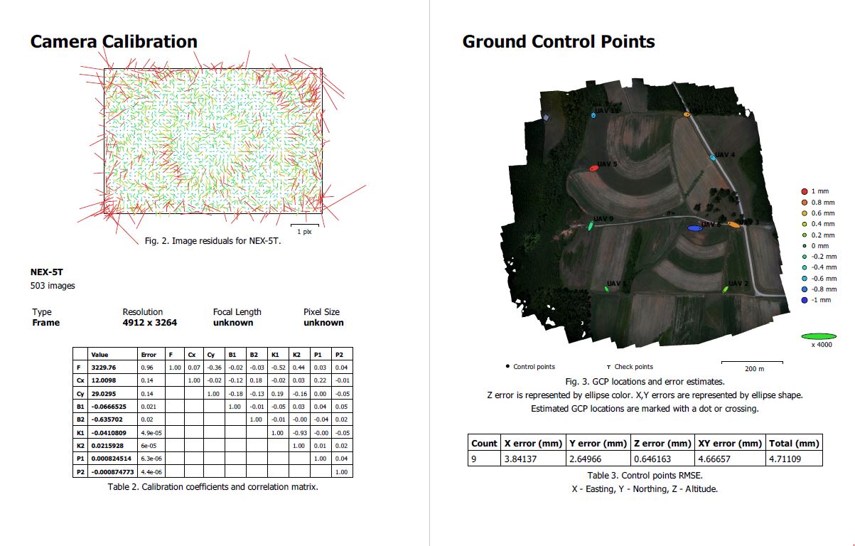
Processing report
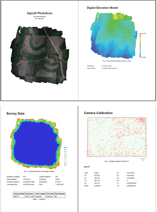
Includes:
- Orthophoto and digital elevation model sketch;
- Camera parameters and survey scheme
- Tie points data export (matching points and panoramas)
- Image overlap statistics
- Camera positioning error estimates
- Ground control point error estimates
Batch processing
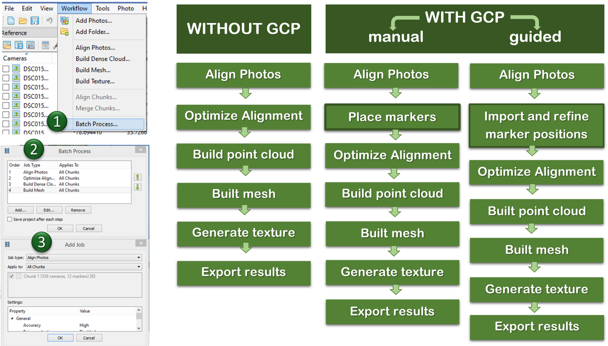
Quality processing with GCPs
- Marker positions are defined by their projections on the source photos;
- After optimizing alignment based on markers, Point cloud generation and other steps need to be performed
- setting up a coordinate system,
- photo alignment optimization,
- measuring distances and volumes,
- marker based chunk alignment.
- more on GCP placing and processing in Agisoft see see intro to the assignment
used for:
What did we learn?
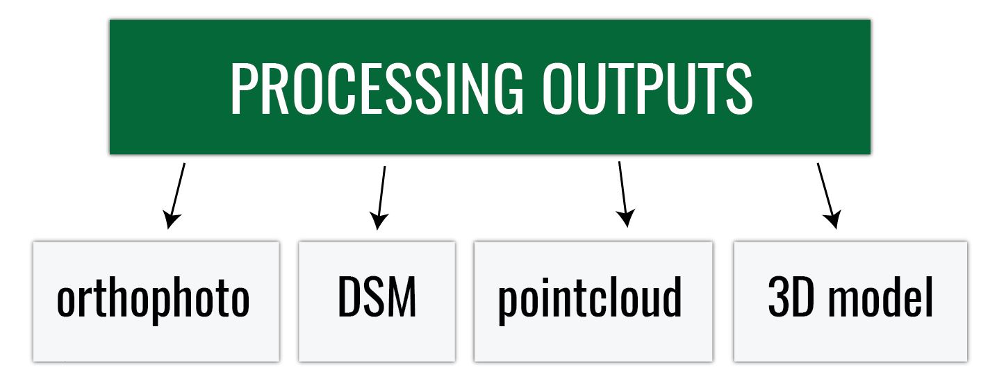
- What is a general workflow for UAS imagery processing
- How do we transform UAS data into orthophoto, DSM, 3D model and pointcloud
- How to process the data in Agisoft Photoscan Professional and how to set proper parameters in the program
