Soil erosion and deposition modeling
ArcGIS workflow
Helena Mitasova, Anna Petrasova, Vaclav Petras, ...
See also GRASS GIS workflow.
start ArcMap
Start->Programs->ArcGIS->ArcMap
Check out a Spatial Analyst Extension license
Under Tools->Extensions make sure there is a check next to 'Spatial Analyst'
Select View->Toolbars->Spatial Analyst to activate the extension
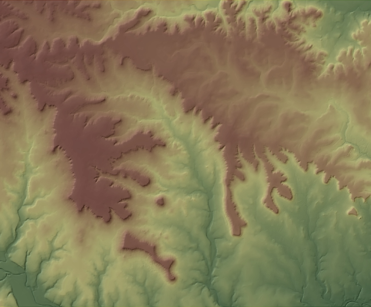
Display the input layers and baseline data
Note: the data need to be clipped to area1 for the tutorial
In ArcMap
Add the raster feature layer: ndvi
Add the raster feature layer: soils_kfac
Add the raster feature layer: elevation
Add the line feature layer: streams
Add the line feature layer: roads
Set your workspace
In ArcMap
Open the ArcToolbox
Set your Workspace and Scratch Workspace to .\usped
Hint: Geoprocessing->Environments->Workspace
Compute slope map using the Slope function
Select 'Spatial Analyst Tools->Surface->Slope'
Set 'Input' to 'elevation'
Set 'Output Raster Dataset' to '.\usped\slope'
keep DEGREES for units
Click 'OK'
Compute aspect map (direction of flow, direction of gradient vector) using the Aspect function
Select 'Spatial Analyst Tools->Surface->Aspect'
Set 'Input' to 'elevation'
Set 'Output Raster Dataset' to '.\usped\aspect'
keep DEGREES for units
Click 'OK'
Compute the flow accumulation map Flowacc
Using the Spatial Analyst Extension, perform the following:
Compute Fill input=elevation output=fill_elevation
Compute FlowDirection input=fill_elevation ouput=flowdir
Compute FlowAccumulation input=flowdir output=flowacc
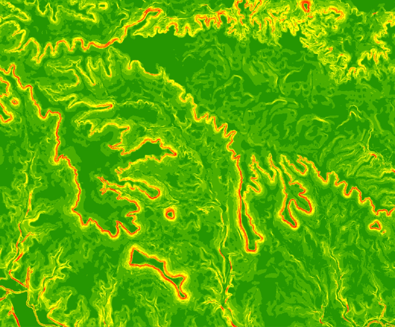
Compute topographic component (factor) of sediment transport capacity LST
Build an expression for sflowtopo using the Raster Calculator
For the exponents use m=n=1, resolution is 10.
flowacc" * 10. * Sin("slope" * math.pi/180.0)
output raster = sflowtopo
Click "OK"
OR use m=1.3 and n=1.2 for study areas with extensive rills,
in this case, channels/streams will have large erosion rates due to high values of flowaccumulation
Power("flowacc" * 10. , 1.3) * Power((Sin("slope" * math.pi/180.0)), 1.2)
output raster = sflowtopo_rill
Click "OK"
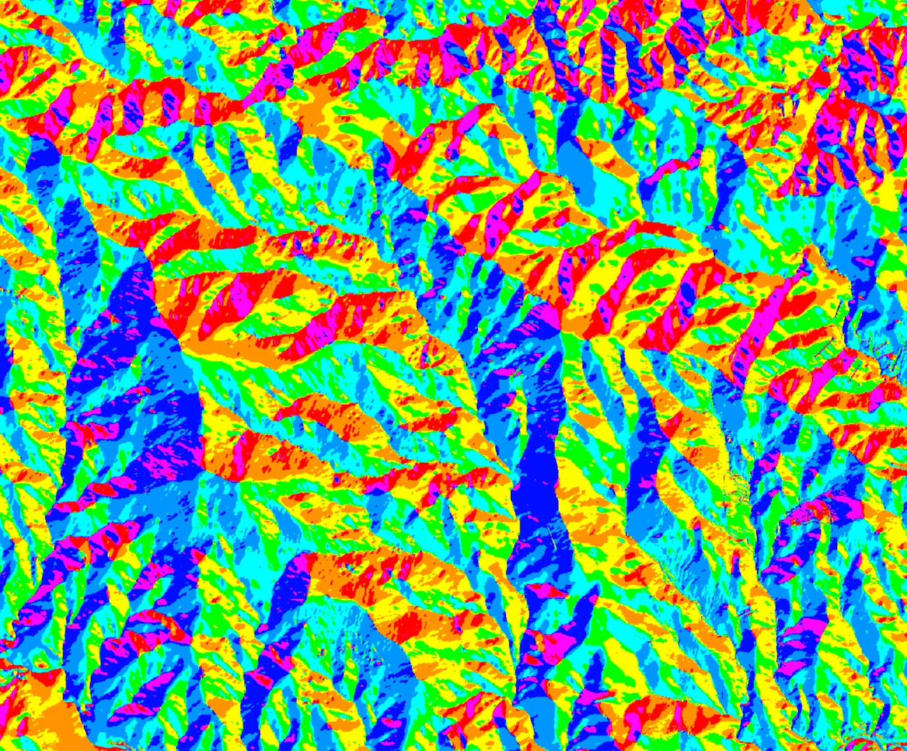
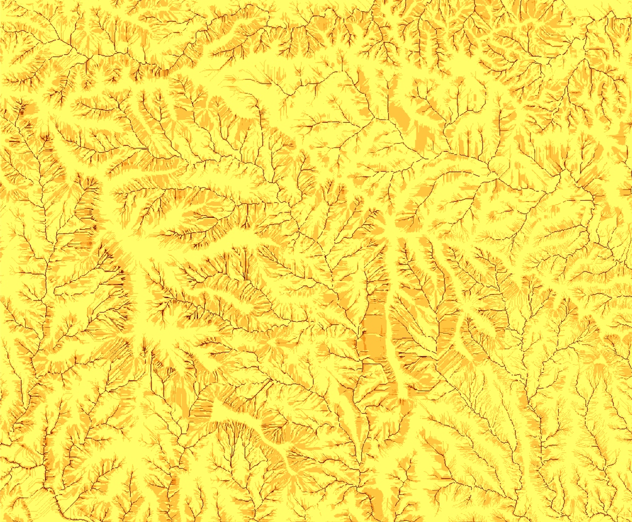
Compute sediment flow by combining the rainfall, soil and land cover factors
with the topographic sediment transport factor
Build an expression using a constant value of 270. for rainfall intensity factor
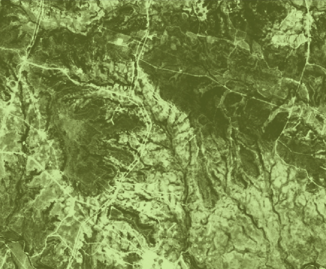
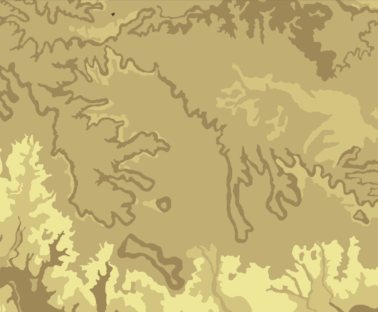
270. * "sflowtopo" * "soils_kfac" * "cover_cfac"
output raster = sedflow
Click "OK"
The images show "sflowtopo", "cover_cfac", and "sedflow"

Compute components of sediment flow in x and y direction
Build an expression for: sedflow_x
"sedflow" * Cos((- "aspect" + 450.) * math.pi / 180.0)
Output raster = sedflow_x
Click "OK"

Build an expression for: sedflow_y
"sedflow" * "Sin((- "aspect_1m" + 450.) * math.pi / 180.0)
Output raster = sedflow_y
Click "OK"
compute components of change in sediment flow in x and y direction
as partial derivatives of sediment flow field, derived from slope and aspect - see eqs 1,2,3 from here:
http://www4.ncsu.edu/~hmitaso/gmslab/reports/cerl99/rep99.html
In ArcToolbox
Select 'Spatial Analyst Tools->Surface->Slope'
Set 'Input' to 'sedflow_x'
Set 'Output Raster Dataset' to '.\usped\sedflow_x_slope'
Keep DEGREES for units
Click 'OK'

Select 'Spatial Analyst Tools->Surface->Aspect'
Set 'Input' to 'sedflow_x'
Set 'Output Raster Dataset' to '.\usped\sedflow_x_aspect'
Click 'OK'

In ArcToolbox
Select 'Spatial Analyst Tools->Surface->Slope'
Set 'Input' to 'sedflow_y'
Set 'Output Raster Dataset' to '.\usped\sedflow_y_slope'
Keep DEGREES for units
Click 'OK'

Select 'Spatial Analyst Tools->Surface->Aspect'
Set 'Input' to 'qsy'
Set 'Output Raster Dataset' to '.\usped\sedflow_y_aspect'
Click 'OK'

Using the 'Spatial Analyst->Map Algebra->Raster Calculator:
Build an expression for: sedflow_dx
Cos((- "sedflow_x_aspect" + 450) * math.pi / 180.0) * Tan("sedflow_x_slope" * math.pi/180.0)
Output raster = sedflow_dx
Click'OK'

Build an expression for: sedflow_dy
Sin((- "sedflow_y_aspect" + 450) * math.pi / 180.0) * Tan("sedflow_y_slope" * math.pi/180.0)
Output raster = sedflow_dy
Click 'OK'
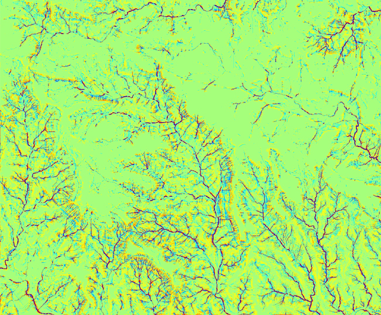
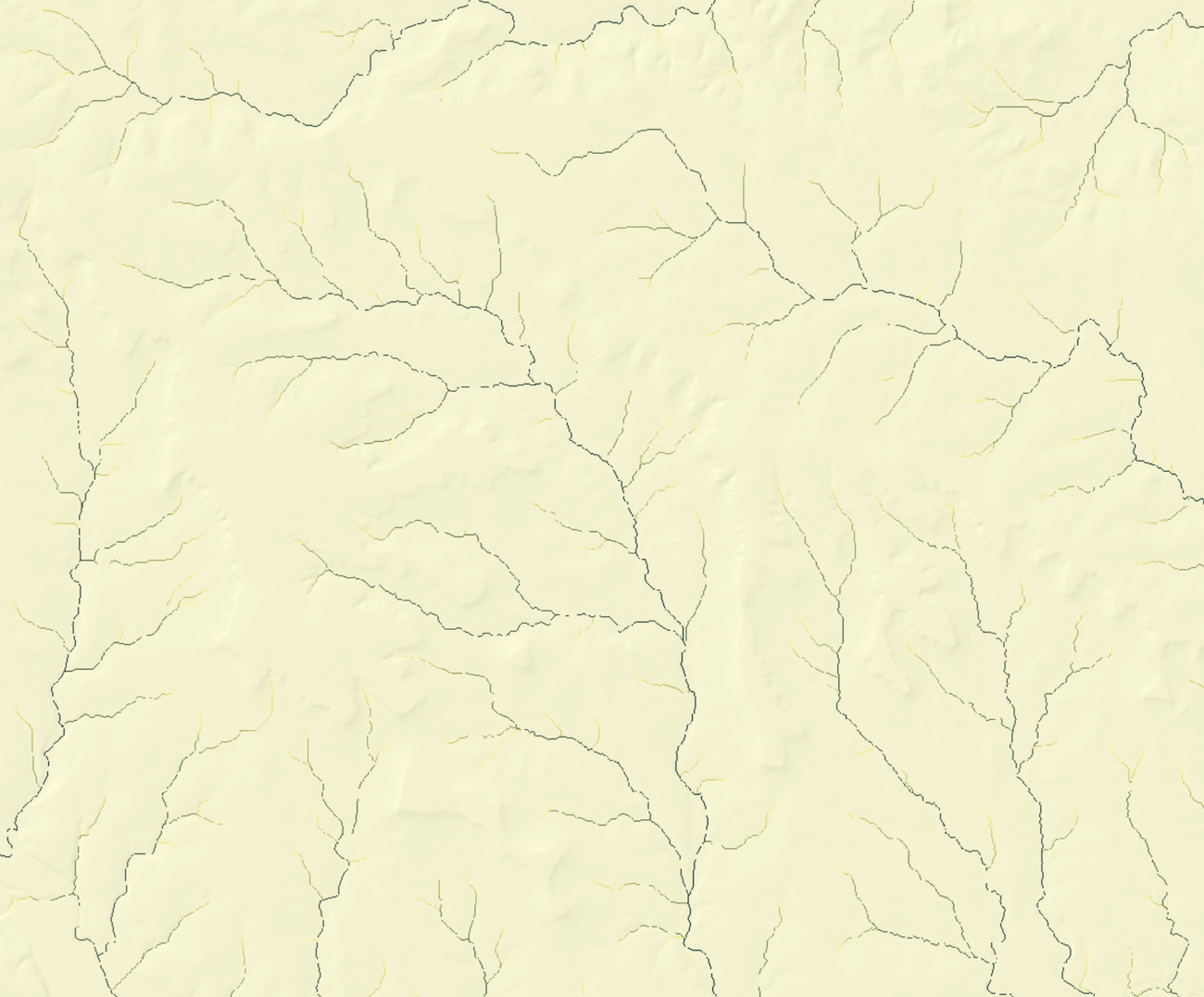
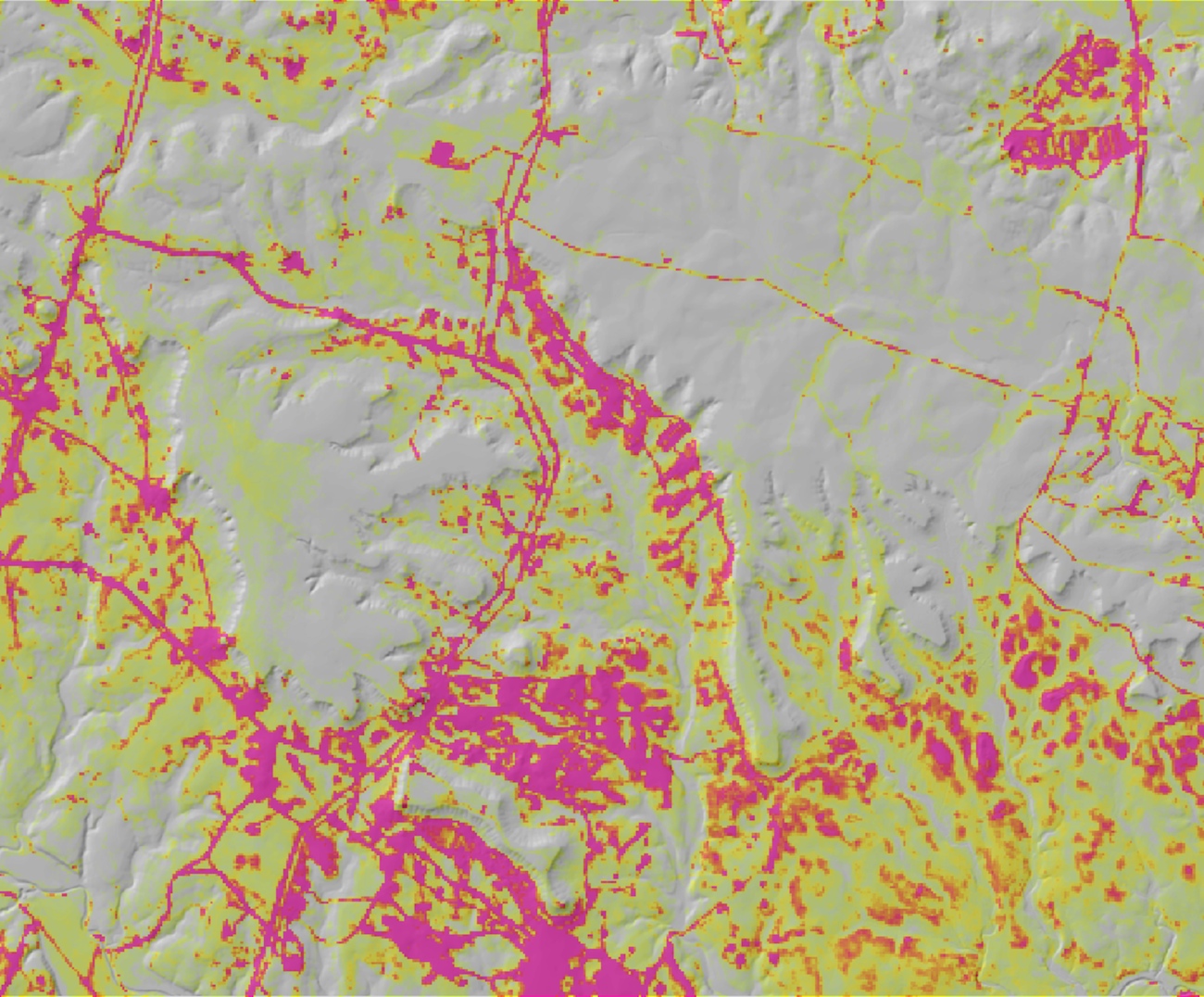
Compute net erosion depositionBuild an expression for: erosion_deposition "sedflow_dx" + "sedflow_dy" Output raster = erosion_deposition Click 'OK'
Assign an appropriate color scheme to the erosion_deposition raster
Change to the actual color ramp
Open Layer Properties for the erosion_deposition layer
Under the Symbology tab
Select Classified from options (Unique Values, Classified, Stretched, Discrete) in the left column
Set Classes to 11
Choose a broad, divergent color ramp from the Color Ramp drop down field
that ranges from brown grading through white to green
Click on Classify
Edit the eleven break values (located in column on far right in Classification dialog to:
-250000.00  (data minimum)
-50.00
-5.00
-1.00
-0.10
0.10
1.00
5.00
50.00
330000.00    (data maximum)
Click OK
Click Apply
You should now see the erosion and deposition areas rendered with a good contrast.
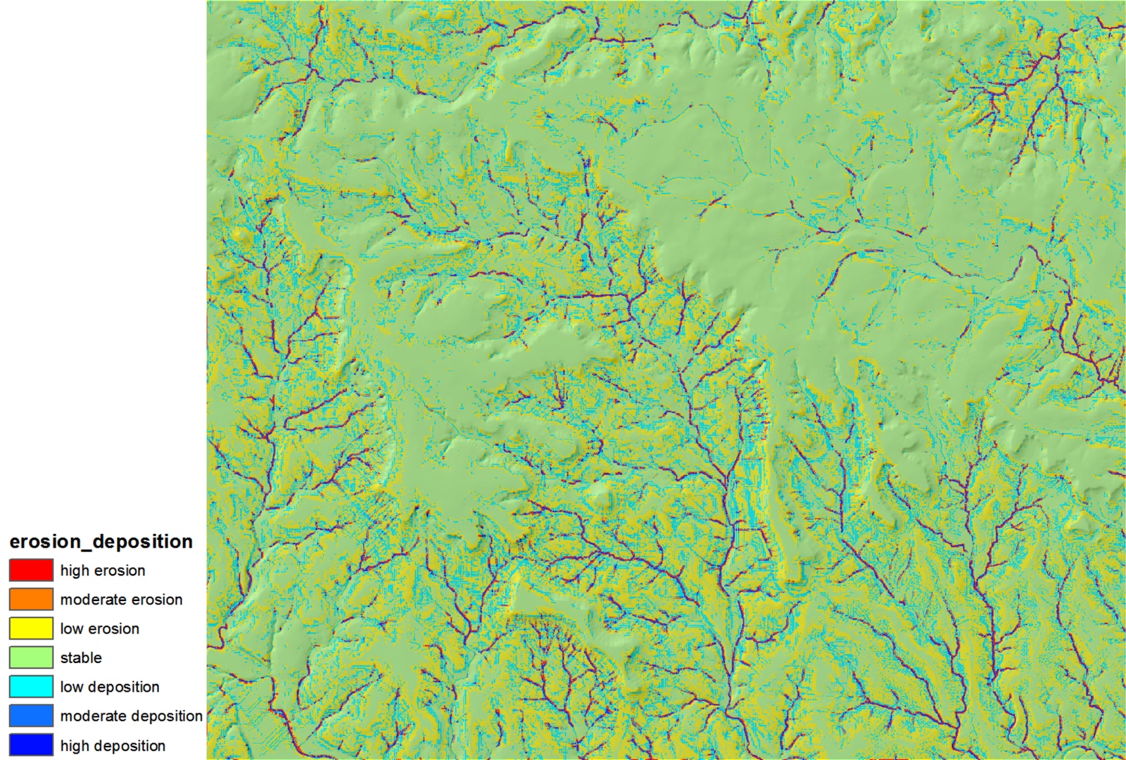
Classify the erosion and deposition layer into pre-defined classes
ADD CLASSIFICATION HERE